Gear Train : Gear Ratio, Speed and Torque Calculations

A gear train uses two or more gears to transmit rotational motion and power from an input shaft to an output shaft. By selecting different gear sizes, a gear train can increase torque, increase speed, or change the direction of rotation. Gear ratio is used to determine the relationship between input and output speed and torque.

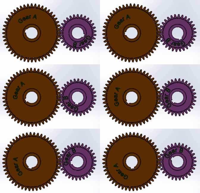
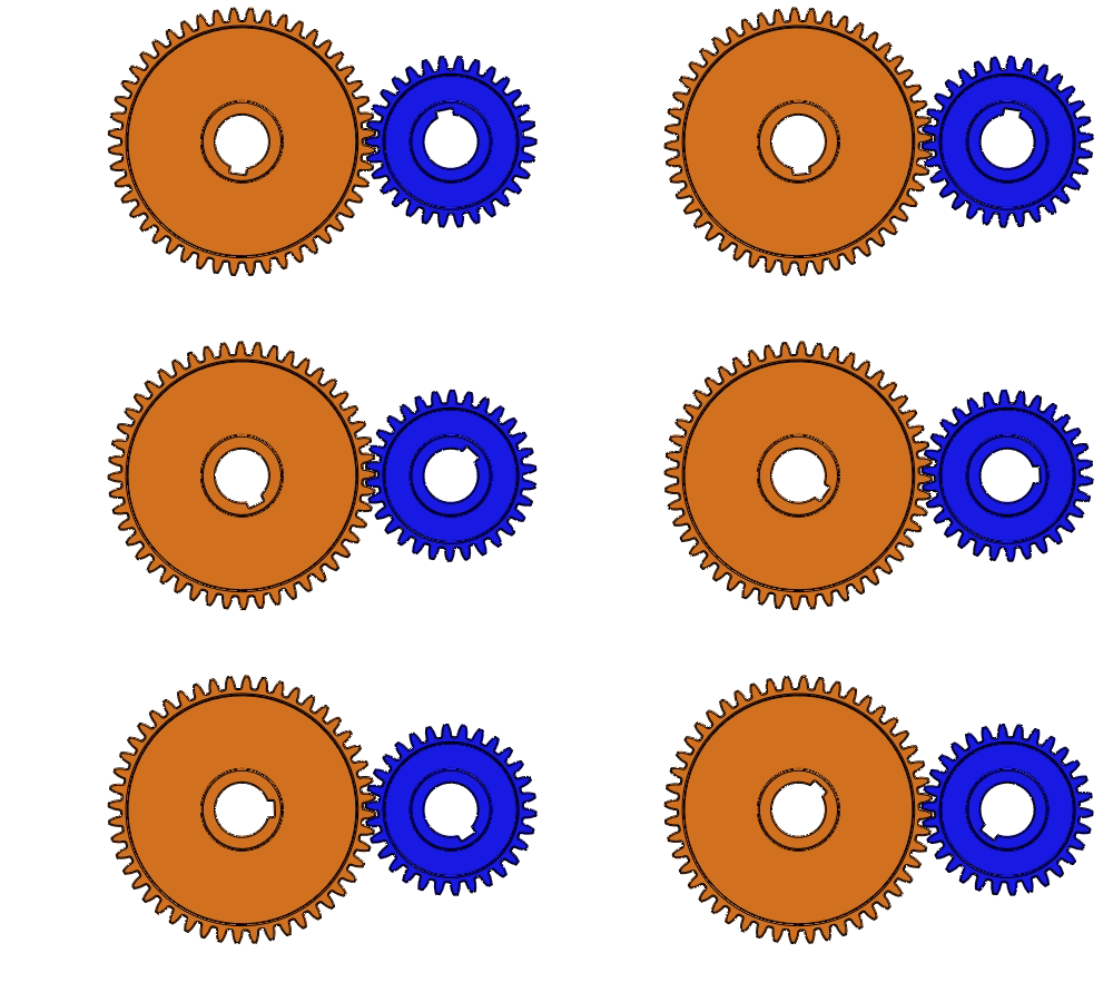
This image shows spur gear in motion
Spur Gear in Motion
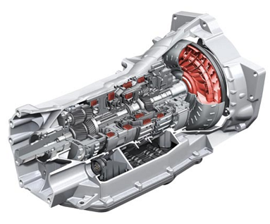
this image shows a Tiptronic Transmission
A Vehicle Gear Box

For example, a gearbox is a type of gear train. Its application is to change (increase or decrease) the car’s speed by changing the engine torque. Any change in torque depends on what gear you are driving your vehicle. This article covers the gear train, gear ratio, speed, and torque calculations.

To understand the gear ratio, we suggest you read this article on gear Terminology ( Various Terms Used in Gears) and Various Types of Gears.

Law of Gearing

The Law of Gearing states that the angular velocity ratio between mating gears remains constant. To achieve the law of gearing or constant angular velocity, a normal at the point of contact between mating gear teeth always passes through the pitch point. Here the Pitch point is the point of contact between mating gear pitch circles.

We can conclude the following relation if the angular velocity of the mating gear is constant :
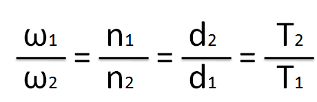
This image shows a relationship between angular velocity, speed and torque of a gear train

Where ω1 and ω2: Angular Velocity in radian/sec for driver and driven gear.

n1 and n2 = Gear Speed in RPM for driver and driven gear.

d1 and d2 = driver and driven gear diameter.

T1 and T2 = Number of Teeth on driver and driven gear.

Gear Ratio

The Gear ratio is the ratio of the number of teeth of the driven or output gear and the driver or input gear. It is used to calculate the speed and torque of the output shaft when input and output shafts are connected using a gear train.

The driver or Input gear is the gear where we apply the torque. Driven or output gear is a gear where we use the applied torque. And the gears used in between the driver and driven gears are known as idler gears.
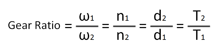
This image shows the formula to calculate gear ration of a gear train

Gear Ratio and Speed

Power transmission through the gear train affects the rotational speed of the output shaft as well.

This image shows a relation between gear ratio and speed of the output shaft

Therefore:

Speed of Output Shaft = Speed of input Shaft / Gear Ratio
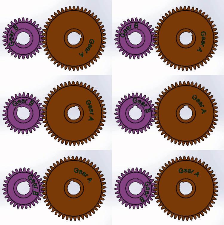
This image shows the movement of reduction gear drive
Gear Reduction

As shown above, if the number of gears on the output shaft is greater than the gears on the input shaft. This arrangement is also known as reduction gear Drive. In this arrangement, the output shaft will have a low speed compared to the input shaft.

This image shows Spur Gear arrangement to increase the speed of output shaft.
Spur Gear arrangement to increase speed

Output shaft speed will be high, compared to the input shaft speed, when the number of gears on the output shaft is less than the gears on the input shaft.

Gear Ratio and Torque

According to the law of gears, in a Gear Train, the Ratio of output torque to input torque is also constant and equal to the Gear ratio. Therefore if the input torque is known, we can calculate the output torque by multiplying the input torque with the gear ratio.
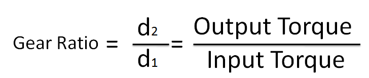
This image shows a calculation formula for torque if gear ratio is known

This is only true for an ideal gear train with 100% efficiency. In the real world

Output Torque = Input Torque × Gear Ratio × Efficiency
Gear Train Types and their Calculation

A gear train consists of a series of gears to transfer power from one shaft to another. For example, power from the engine is transferred to the wheels through the gearbox. Here are the four different types of the gear train.

  1. Simple Gear Train
  2. Compound Gear Train
  3. Reverted Gear Train
  4. Planetary Gear Train

1) Simple Gear Train: Gear Ratio Calculations

A simple gear train is a gear train with two or multiple gears between input and output shaft.

1.1) Two Gear Train 

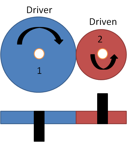
Two Gear Train is a type of Simple gear train with two connected gears. For Example, As shown below in a two-gear train. Gear-1 is the driver, and Gear-2 is the driven gear. When the driver gear rotates in a clockwise direction, the driven gear starts rotating in an anti-clockwise direction.

For external spur gears:

Gear 1 → Gear 2 → Gear 3

Each external gear reverses direction. Therefore:

  • 2 gears → output opposite input
  • 3 gears → output same as input
  • 4 gears → output opposite input

This is especially useful when discussing idler gears. You currently introduce idler gears but don’t explain one of their most useful characteristics:

  • An idler gear changes rotational direction and/or helps with center distance, but does not change the overall gear ratio in a simple gear train.

Question: Calculate the Speed and torque of the output shaft for a simple gear train if the number of teeth on the driver and driven gear are 40 and 20. And Driver gear is rotating with 100 rpm and 10 N-m torque.

Number of teeth on driver Gear (T1) = 40

Number of teeth on driven Gear (T2) = 20

Speed of Driver Gear (n1) = 100 rpm

The torque acting on the driver gear =  10 N-m

This image shows a gear train with two gears.
Two Gears Train

Gear Ratio Calculation

Formula for Gear ratio calculation

GR = T2 / T1 = 20/40 = 0. 5

Output Gear Speed Calculation

Speed of Output Shaft/Gear = n1/GR = 100/0.5 = 200 rpm

Output Shaft/Gear Torque Calculation

Torque generated by Driven gear = GR × Torque Generated by driver

= 0. 5  × 10 = N-m

Note: Gear-ratio terminology is used with different conventions in engineering references. In this article, we define gear ratio as driven gear teeth / driver gear teeth. All speed and torque equations below follow this definition.

1.2) Multi Gear Train

Multi-gear trains consist of more than two gears to transfer motion from one shaft to another. The resultant gear ratio can be calculated by multiplying individual gear ratios.

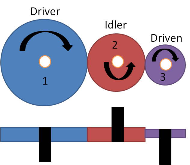
Question:  Calculate the gear ratio for multi-gear trains if the number of teeth on the driver, idler, and driven gear is 40, 20, and 10, respectively.

This image shown a multi gear train
Multi Gear Train

Given Number of teeth

T1 = 40, T2 = 20, T3 = 10

Gear Ratio (GR) Calculation for Multi gear Train

Step-1: Calculate Gear-Ratio between Gear-1 and  Gear-2 (Driver and Idler).

GR(1-2) = 20/40 = 0.5

Step-2: Calculate GR between Gear-2 and  Gear-3 (Idler and Driven Gear).

GR(2-3) = 10/20 = 0.5

Step-3: By Multiplying gear-ratio between 1 to 2 and 2 to 3. We will get resultant GR between Driver and Driven Gear.

Resultant Multi Gear Train GR = 0.× 0.5 = 0.25

From the above, calculated gear ratio we can calculate the speed and torque at output gear.

2) Compound Gear Train: Gear Ratio Calculations

Compound Gears consist of more than one gear on a single axis. Gears mounted on the same shaft rotate at the same angular speed, but they do not necessarily transmit the same torque.

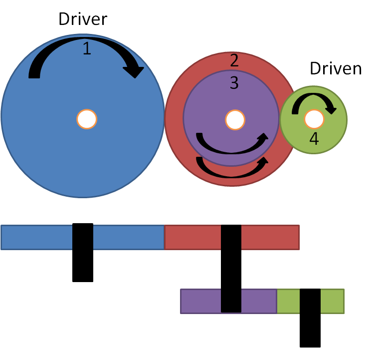
Question: Calculate the gear ratio for the compound gear train if the number of teeth on the driver and driven gear are 40 and 10 with one compound gear. Compound gear has total of two gears. The 1st compound gear connected to the driver has 30 teeth, and the 2nd compound gear connected to the output has 20 teeth.

This image shows a compound gear train
Compound Gear Train

Given number of teeth

T1 = 40, T2 = 30, T3 = 20, T4 = 10

Gear Ratio Calculation For Compound Gear

In the above example, Gear-2 and Gear-3  are on the same shaft.

Step-1: Calculate Gear Ratio between Gear-1 and Gear-2

GR(1-2) = 30/40 = 0.75

Step-2: Calculate GR between Gear-3 and Gear-4.

GR(3-4) = 10/20 = 0.5

Step-3: Multiply GR(1-2) and GR(3-4)

Resultant Compound Gear GR = 0.375

3) Reverted Gear Train.

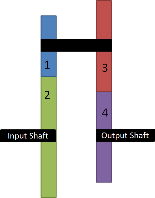
This image shows the arrangement of riverted gear train
Reverted gear train

Reverted gear trains are a type of compound gear train in which input and output shafts are on the same axis. In the above example, gear-1 and gear-3 are on the same axis.

They are used to achieve a high gear ratio within a limited space. The reverted gear train gear ratio is calculated similarly to the compound gear train.

To sum up, the gear ratio is used to calculate the resulting gear speed and torque. The gear ratio of a gear train depends on the number of teeth on the driver, idler, and driven gear.  We suggest you first read this article on Reduction Gears.

Got Questions? 

We will be happy to help.

If you think we missed Something? You can add to this article by sending a message in the comment box. We will do our best to add it to this post.

After understanding this article, we suggest you take this exam to validate your knowledge and understanding.

4 Responses

Add a Comment

Your email address will not be published. Required fields are marked *