An increase in heat dissipation rate and reduction in overall form factor has made thermal management of electronics products a challenging task. Heat sinks cool electronics devices by increasing heat dissipating surface area. In this article, we will discuss how to select a heat sink by calculating heat sink thermal Resistance?
How does a Heat Sink work?
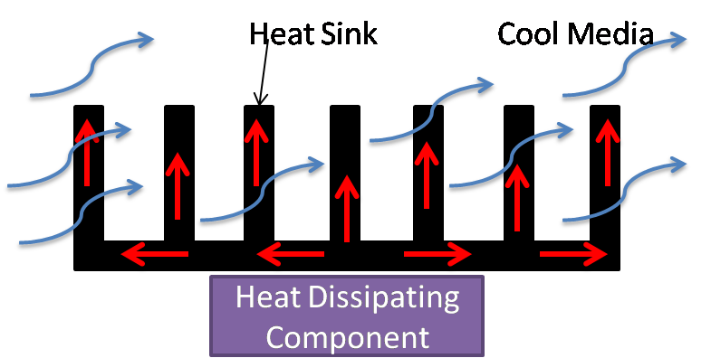
The Heat sink works by increasing the heat-dissipating area of the heat-dissipating component. It enables the heat sink to transfer more heat to a colder environment. The rate of heat transfer from a heat sink depends on the following factors:
- Heat Sink material thermal conductivity
- Available surface area
- Natural or forced convection (air-speed)
- Ambient conditions such as air temperature.
Heat Sink Thermal Resistance Calculations
Thermal resistance is a property of a material or body by which a material resists heat flow. It measures the temperature difference between two ends of a body. Similarly, the thermal resistance of a heat sink measures the heat transfer efficiency of a heat sink in a thermal circuit. To select a heat sink, firstly thermal resistance of the heating circuit is calculated.
Mathematically thermal resistance of a body is equal to the ratio of temperature difference and heat generated.
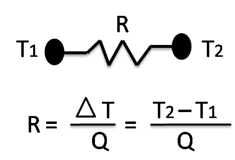
R = Thermal resistance (°C/W), Q = Generated heat (watt), (T2-T1) = Difference in temperature.
Calculation of Thermal resistance in series
Rules of electrical resistance in series also apply to thermal resistance. To understand this, let’s consider an example of the cooling of the heat-dissipating chip on the PCB.
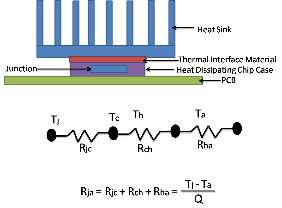
From the above Heat Sink Thermal Circuit:

Q : Total power or heat dissipation in watt.
Tj : Device / chip junction temperature (°C).
Tc : Device / chip case temperature (°C).
Th : Heat sink temperature (°C).
Ta : Ambient air temperature (°C).
Rja : Junction to air thermal resistance.
Rjc : Junction to chip thermal resistance.
Rch : Chip to heat sink (Interface material) thermal resistance.
Rha : Heat sink to air thermal resistance.
| Typical Values of Commonly used Electronic Package Thermal Resistance | ||
|---|---|---|
| Electronics Package | (Rjc) Junction to Case (°C/W) | (Rca) Case to Air (°C/W) |
| TO-3 | 5 | 60 |
| TO-39 | 12 | 140 |
| TO-223 | 30.6 | 53 |
| TO-263 | 23.5 | 50 |
**Please note these values are for indicative purpose only please refer package datasheet.
Heat Sink Thermal Resistance Calculator
Heat Sink Selection
Selection of heat sink is done by comparing the values of the thermal resistance from junction to air (Rja) and the sum of the thermal resistance of the junction to case (Rjc) & case to air(Rca)
If
Rjc + Rca < Rja ; Heat sink is not required.
If
Rjc + Rca > Rja ; Heat sink is required.
Selected heat sink thermal resistance (Rha) should always be greater than the total calculated required thermal resistance.
How to Improve Heat sink Thermal Performance
We can increase Heat Sink thermal performance by improving conductive, convective, or radiative heat transfer. We should consider the following points to improve heat sink performance without increasing its size.
1) Heat Sink Design : Arrangement, Shape and Size of Fins
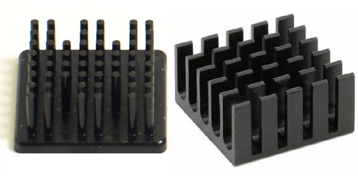
We can improve heat sink performance by improving the airflow in the heat sink. The heatsink fin’s size, design, and orientation have a direct impact on the airflow. Therefore we can improve heat sink performance just by improving the heat sink fins design.
2) Air Flow Direction
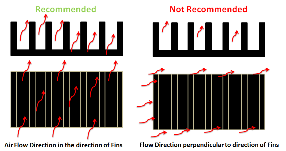
The direction of airflow also has an impact on the performance of the heat sink. Airflow in the direction parallel to fins is recommended because, in this arrangement, air moves along a longer distance through fins. Whereas when air flows in the direction perpendicular to fins. Air does not reach the inside area of the heat sink.
3) Airflow Speed and Type
The type of airflow (natural or forced convection) affects the heat sink thermal performance. We can reduce heat sink thermal resistance by increasing the airspeed.
4) Heat sink Material
Highly conductive material reduces heat sink thermal resistance. For similar geometry, copper heat sinks thermal resistance is less than the aluminum heat sink. Therefore heat sink performance can be increased by using a highly conductive material.
5) Thermal interface Materials
Thermal paste or thermal pads fill air gaps between the heat sink and the heat-dissipating chip. Heat sink thermal performance can be increased by selecting a highly conductive thermal paste/pad.
6) Heat Sink attachment Methods
Heat sink thermal performance can be increased by selecting an appropriate method of attaching a heat sink to heat-dissipating components. Heat sink attachment methods include :
To sum up, Because of the miniaturization of electronics products. Dissipation of heat from electronics products is becoming a challenging task. Therefore Selection of the right heat sink ensures the reliable operation of heat-dissipating components.
Got Questions? We will be happy to help.
If you think we missed Something? You can add to this article by sending a message in the comment box. We will do our best to add it to this post.
Hi Team,
Thanks for your wonderful article on this, I need one example to get more clarified on this. Can you please provide me a one example with proper values, which will help us to apply quickly in our products.
Again Thanks for your extended support.
With regards,
Yuvarajsha M
Please let us know what problem you are facing. We will consider that as example and solve it.
Design a heat sink for a LM1875
This is a nice article. Can you share the calculations involved when it comes to a complete module?
Thank you so much. This was such a helpful article and virtually the only one with the necessary detail and depth of explanation that I could find. Excellent work.
Great work – I have a similar problem, wondering what thermal resistance parameters to use to determine if I need a heat sink or not.
When could AR make its presence recognized all through the on-line gaming sector?
Kеep onn writing, gгeat job!