What is Deep Drawing in Sheet Metal?
Deep Drawing is a sheet metal forming operation where sheet metal blank is drawn into hollow shapes by utilizing the combination of tensile and compressive forces.
We can consider a component as the deep-drawn if the depth of the drawn part is greater than or equal to the part radius.
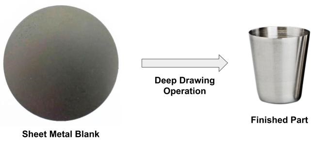
Deep drawing operation in sheetmetal is a widely used sheet metal forming Operations in the automotive and consumer goods sector to manufacture sheet metal parts. The deep-drawing process converts a sheet metal blank into a cylindrical component with one side open.
Applications
The deep drawing process is used to manufacture sheet metal parts in large volumes for various industries. Following are some of the application examples:
- Automotive components.
- Fluid and air control valves.
- Electronics components such as EMI-EMC shields.
- Cup and housing for needle and roller bearing.
- Aerospace and defense components.
Advantages
The deep drawing process in sheet metal has the following advantages when it is used to manufacture sheet metal parts in high production volume.
- Manufacture hollow cylindrical, rectangular, square, and other complex geometries.
- Low manufacturing cost.
- Less material consumption.
- High productivity.
- Precise parts.
- High strength and minimum weight parts.
- Low tool construction cost compared to progressive stamping tool.
Sheet Metal Deep Drawing Process
Compressive and tensile forces are used in the deep drawing operation to convert a flat sheet metal blank into a hollow body. Following sheet metal forming operation can convert a sheet metal blank into a deep-drawn sheet metal part. After sheet metal forming, part finishing operation is done (trimming, cutting, cleaning, and a powder coating)
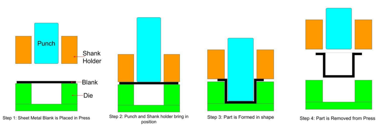
Step-1
After blanking, place the sheet metal blank inside the die.
Step-2
In the next step, the shank holder grips the sheet metal blank in between the die and shank holder with the required pressure.
Step-3
After gripping the sheet metal blank with the required pressure. Deep-Drawing punch stretches the sheet metal blank inside the die. During this operation, reduce the shank holder pressure continuously to ensure the free movement of material. High shank holder pressure can cause wrinkles in sheet metal parts. Thinning is a common problem during stretching operations.
Step-4
After sheet metal drawing operation, remove the finished part from the die and send it for final finish operations.
Sheet Metal Deep Drawing Calculations
Following calculations are required during the design and manufacturing of deep-drawn sheet metal parts.
Sheet Metal Blank Size Calculations
Sheet metal deep drawn part blank size is calculated considering the blank surface area is equal to the finished part surface area.
Blank Surface Area = Finished Part Surface Area
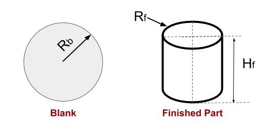
Consider an example of the cylindrical cup blank size calculation when the size of the finished part is known.
Blank size for the deep drawing sheet metal part is calculated in the following steps.
Step-1: Calculate Blank Surface Area
Blank Surface Area = π Rb²
Step-2: Calculate Finish Part (Cup) Surface Area
Finish part Surface Area = π Rf² + 2 π Rf Hf
Step-3: Keep Blank Surface Area is equal to the Finish Part Surface Area
Π Rb² = π Rf ² + 2 π Rf Hf
Rb = √ Rf (Rf + 2 Hf)
In this way, unknown values from the above equation can be calculated.
Deep Draw Reduction Ratio Calculations
A part requires multiple drawing operations if the sheet metal part depth is large. You can calculate the total number of draw operations using the Draw reduction ratio.
Draw Reduction Ratio Formula

The best way to calculate the draw reduction ratio for a part is by using simulation. But as a rule of thumb draw reduction ratio for the first, second, and third draw can be considered 50%, 25%, and 20%. Please note higher draw reduction ratio can cause various manufacturing defects.
Maximum Deep Drawing Force Calculation Formula
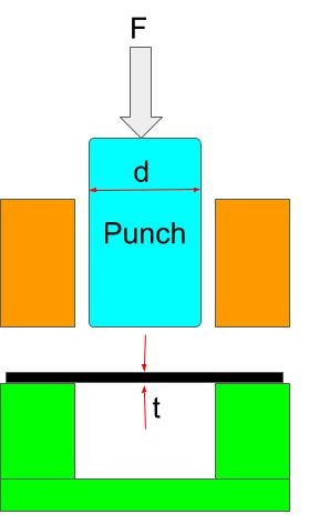
You can calculate the maximum force required to draw sheet metal parts using the following formula. From these force calculations, you can calculate the machine tonnage to manufacture the part.
Maximum Drawing Force = π × (d+t) × t × UTS
d = Punch Diameter
t = Blank Thickness
UTS = Ultimate Tensile Strength for the sheet metal Material
Deep Drawing Calculator
Deep Drawing Calculation Examples
Problem: Calculate the blank diameter and number of Drawing operations required to deep draw a cup of diameter 50 mm and depth 60 mm?
Solution:
Cup Diameter = 50 mm, Cup depth = 60 mm
As Discussed Above:
Rb = √ Rf (Rf + 2 Hf)
= √ 25(25 + 2 × 60) = 60.2 mm
Blank Diameter = 60.2 × 2 = 120.4 mm
Calculation for number of drawing Operation:
Assuming for first draw Draw reduction Ratio (DRR) = 0.5
DRR × Blank Diameter = (Blank Diameter – Punch Diameter)
0.5 × 120.4 = 120.4 – Punch Diameter
Punch Diameter = 60.2
Since in single draw operation maximum 60.2 mm height cup can be deep drawn. Therefore only one drawing operation is enough to manufacture this part.
Common problems during deep drawing process
Following defects can be visible on deep-drawn sheet metal parts if you do not follow deep-drawing part design guidelines or manufacturing process parameters are not ok.
Wrinkling
Wrinkling defects occur in the vertical wall or flange of deep drawn sheet metal parts due to high radial and tangential compressive stresses. It can be prevented by good tool and process design.
Tearing and Thinning
Tearing and thinning occur in the inner section of the deep drawn part due to high shank holder pressure that restricts the free movement of material. Which results in high tensile stresses in that region. Tearing can also occur because of the small corner radius.
Surface Defects
Surface defects such as scratch marks, tool and die marks can occur due to the small clearance between the tool and die or low lubrication.
Earing
Earing defect causes irregular features on the flange of deep drawn parts. It occurs due to the anisotropic behavior of the material.
We will keep adding more information on deep drawing operation in sheet metal. Add your suggestions, comments, or questions in the comment box. We suggest you also read this article on the sheet metal material selection guide.
Sir,I need to do the cup dia 39.6 internal diameter and 41 outer diameter x cup length 70 mm.
Please guide no.of drawing and various punch dia
Sorry Jai, I do not have expertise in tool and die design. I can not help in this.
very useful
intrested in deep draw calculations
As your calculater it’s give 15 ton force, but machine manufacture saying it’s should be 100 ton.
It’s big confusions…..
If the manufacturer says 100 Ton, Go with 100 tons only. If you please show the problem in detail, we can tell tell you why difference is coming
Sir,
SS 202 Circle diameter 216mm
Thickness is 0.25mm
Deep is 90mm.
It’s belly shape container.
Machine manufacture saying it’s need 80 to 100 ton hydraulic press.
But your calculater says it’s 8 to 15 ton requaird.
So it’s some confusion.
Sir,
SS 202 Circle diameter 216mm
Thickness is 0.25mm
Deep is 90mm.
It’s belly shape container.
Machine manufacture saying it’s need 80 to 100 ton hydraulic press.
But your calculater says it’s 8 to 15 ton requaird.