GD&T Straightness is a type of foam control tolerance that is used to control the line on a surface/feature or an axis. In other words, straightness controls a condition where all elements of a surface or an axis lies in a straight line.
Datum planes are not required to define straightness. Whereas LMC and MMC modifiers can be used to define the straightness of an axis. Don’t miss this article on the basics of “Geometric Dimension and Tolerance”.
GD&T Straightness of a Surface
When applied to a surface, straightness creates a 2-dimensional tolerance zone. It is used to control the surface of a part and ensures the part is uniform across that surface or feature.
Representation
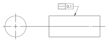
As shown above, Datum planes are not required to define the straightness of a surface and it can be applied to the flat surface of a cylinder or block.
Tolerance Zone
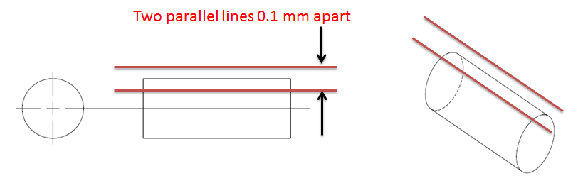
When applied to a surface, straightness creates a tolerance zone of two parallel lines at a distance equal to the tolerance value from the controlled 2D surface. All points of the controlled surface should lie within these two parallel lines.
Applications
Straightness of a surface is generally used with the mating surface where two parts should have a line contact. For example in parts where line contact between two parts is maintained to apply uniform pressure.
How to measure straightness tolerance applied to a surface?
To measure the straightness of a surface. The dial gauge is fixed and part is moved over the surface plate. The total tolerance value will be equal to the variation observed in the dial gauge reading.
For example, If the dial gauge will move by 0.2 mm, the Total part straightness tolerance will be 0.2mm.
GD&T Straightness applied to an Axis
The Straightness of an axis controls the central axis of a part. It defines how much the axis of a part can deviate from its original position.
Representation
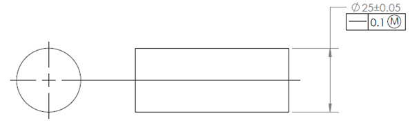
As shown above, to control the straightness of a cylindrical feature datum plane is not required. But LMC and MMC modifiers can be used.
Tolerance Zone
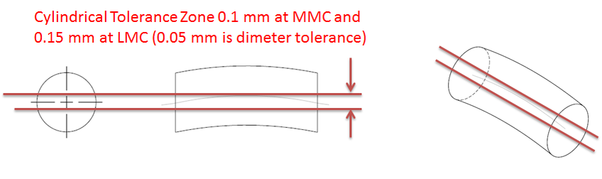
When applied to an axis, straightness creates a 3-dimensional cylindrical tolerance zone around the true central axis of the cylindrical part. All points of the controlled axis should lie within this cylindrical zone. In this way, straightness of an axis controls the bending or twisting in a part.
How to measure straightness tolerance applied to an axis?
To measure the straightness of an axis, the dial gauge is fixed at one position and part is rotated about its axis. It is used to determine the center point of the rotating part. This is continued till the full length of the part. In this way, all central points should lie within the required 3D cylindrical tolerance zone.
We will keep adding more information on straightness tolerance. Please add your suggestions, comments, or questions in the comment box.
Add a Comment