Profile of a line control tolerance in gd&t is a type of profile control tolerance. It simultaneously controls the size, orientation, location, and form of a feature. When applied to a surface, it specifies how much the surface can vary from its original cross-section. Don’t miss this article on the basics of Geometric Dimension and Tolerance.
Profile of Line Control Tolerance Representation
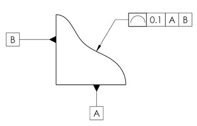
We can use GD&T Profile of line control with or without any datum plane and all-around. But MMC and LMC modifiers are not applicable with it. Click this link to know the symbols used in geometric and control dimensional tolerances.
Tolerance Zone
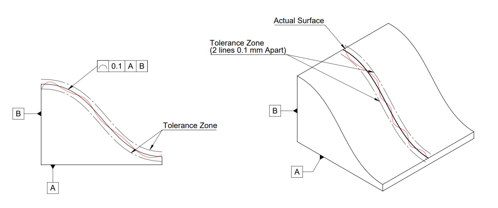
“Profile of a Line Control” in GD&T creates a 2-dimensional bilateral tolerance zone of two parallel curves around the actual surface or feature profile to be controlled. It controls individual line elements of a surface/feature, not the entire surface.
Application
Profile of line control tolerance application is to control complex, curved, or irregular surfaces (such as the profile of turbine blade, and car aerodynamic surfaces) that are difficult to control using linear dimensions. It also works as an alternative to straightness or circularity.
How to measure Profile of Line Control Tolerance?
For relatively simple profiles, you can measure the profile of a line by moving the gauge at the controlled section when referenced to the actual profile. But for complex-profile, quality engineers use CMM, VMM, or 3D scanners.
We will keep adding more information on the profile of line control tolerance in gd&t. Please add your suggestions, comments, or questions in the comment box.
Add a Comment