What is Position Control Tolerance in GD&T?
GD&T Position tolerance controls the variation in the location of a feature from its actual position. We can use MMC, LMC, and projected tolerance modifiers to define the Feature (a hole, slot, or pin) “true position”.
For example, When we define a hole position control in gd&t. It controls the allowable deviation in the hole location from its true position. We suggest you also read the article on the basics of “Geometric Dimension and Tolerance”.
Position Control Tolerance Representation
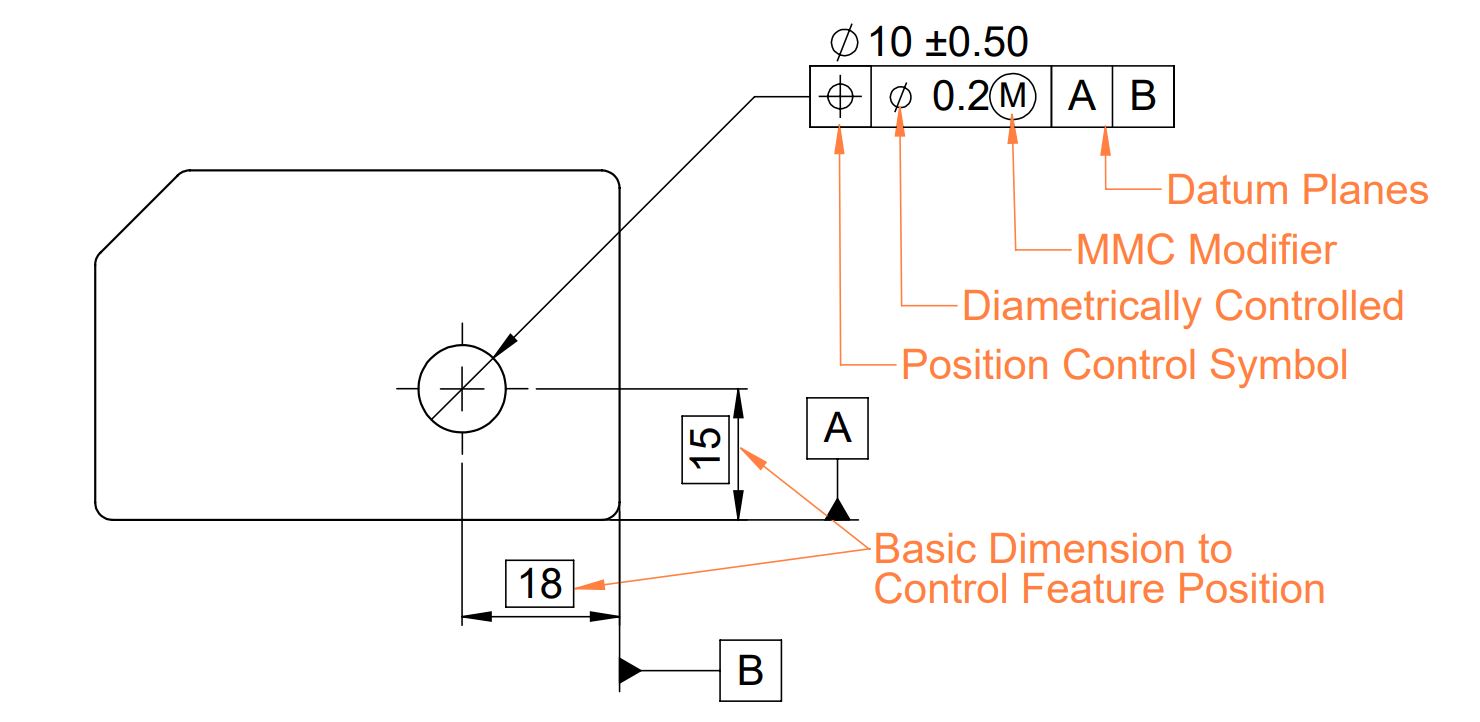
As shown above, You can apply GD&T Position control to a feature such as a slot, hole, or pin to control its location concerning the datum plane. We should consider the following points while specifying position control in engineering Drawing:
- A minimum of two datum planes are required to add position control in part.
- Material Condition (MMC and LMC), projected tolerance, and tangent planes are used to give bonus tolerance.
- Use diameter symbols to make circular or cylindrical tolerance zones.
We suggest you read this article on various GD&T Symbols and their significance.
Tolerance Zone
When Applied without Diameter and MMC Modifier
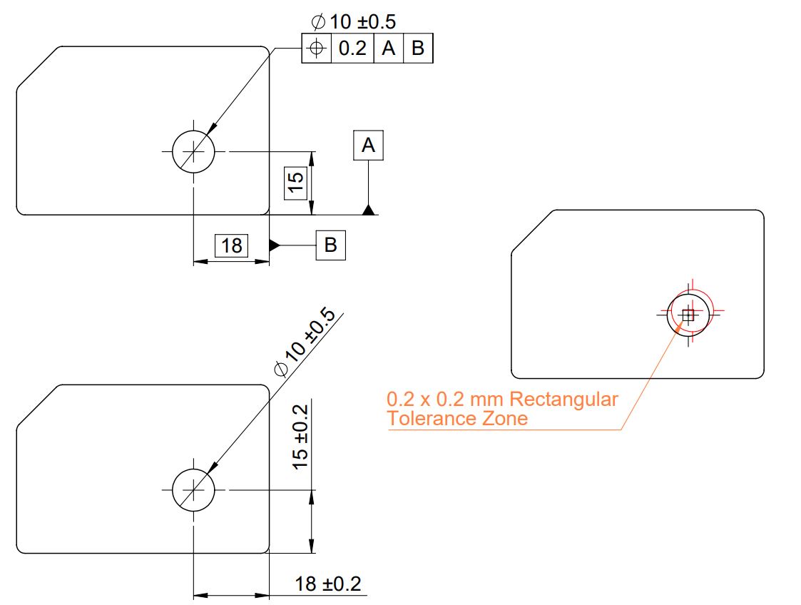
GD&T position tolerance without diameter and MMC modifier create a 2-dimensional rectangular tolerance zone.
The hole axis should lie within this rectangular tolerance zone. It is similar to the linear tolerance in X and Y directions.
When Applied with Diameter Modifier
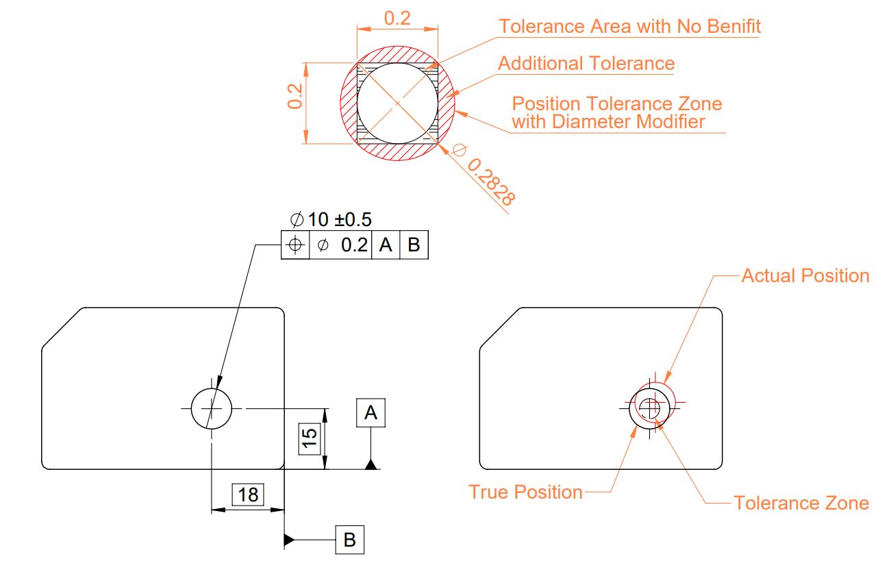
Position tolerance with the diameter modifier creates a circular tolerance zone instead of a rectangular one.
In this way, when we constrain a cylindrical feature using positional tolerance. The diameter modifier gives us the flexibility of giving additional tolerance equivalent to the circle inscribed outside the rectangle.
As shown in the above image:
A 0.2 mm rectangular tolerance is equivalent to the 0.2828 mm circular tolerance zone.
When applied with Maximum Material Condition
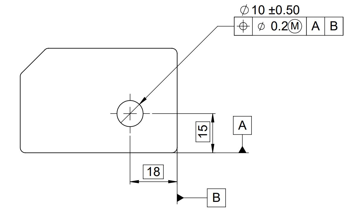
MMC modifier with position control gives a bonus tolerance to the part feature.
Bonus Tolerance Calculation Formula
Bonus Tolerance (For Hole) = Feature actual Size – Feature Size at MMC
Total Allowable Tolerance = Position Tolerance + Bonus Tolerance
| Feature Diameter | Position Tolerance | Bonus Tolerance | Total Tolerance |
|---|---|---|---|
| 9.5 mm (at MMC) | 0.2 | 0 | 0.2 |
| 10 mm (at MMC) | 0.2 | 0.5 | 0.7 |
| 10.5 mm (at MMC) | 0.2 | 1 | 1.2 |
From the above table we can conclude the following points:
- We can add bonus tolerance and position tolerance if the feature size is below MMC.
- As a result, GD&T position control tolerance with the MMC tolerance zone is equal to the sum of position control tolerance and bonus tolerance.
How to measure Position Tolerance?
We can measure Position control tolerance in GD&T similar to how we measure the linear dimensions (Vernier scale, VMM, Coordinate Measuring Machine, etc.).
The feature’s position variation should be within the limits of position control tolerance.
We will keep adding more information on GD&T Position control. Please add your comments, suggestions, or questions on Geometric Dimension and Control Tolerance in the comment box.
Add a Comment