What is Perpendicularity Tolerance in GD&T ?
Perpendicularity-Tolerance in GD&T controls the perpendicularity of a surface feature or an axis with respect to the datum plane.
It controls the variation in a surface from perfect right angle (90º) w.r.t. to datum plane or surface when applied to a surface.
When applied to an axis, it controls the variation in an axis from a perfect right angle (90º) w.r.t. the datum axis or plane.
For example, GD&T perpendicularity is used with hole and pin features to ensure parts fit even in the worst conditions. Don’t miss this article on the basics of Geometric Dimension and Tolerance.
Perpendicularity Tolerance Representation
When applied to a Surface
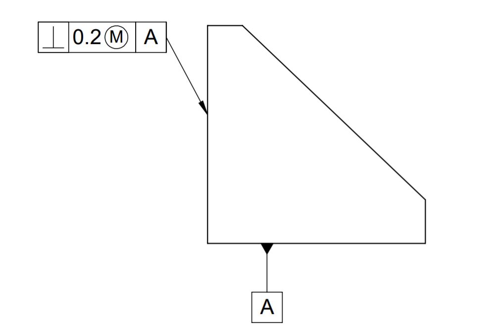
As shown in the above image, perpendicularity can be applied to a surface or line to control its orientation w.r.t. a datum plane or a surface.
In other words, it controls the 90° angle between two lines, surfaces, or multiple planes. LMC and MMC modifiers are used with perpendicularity to provide bonus tolerance.
When applied to an Axis
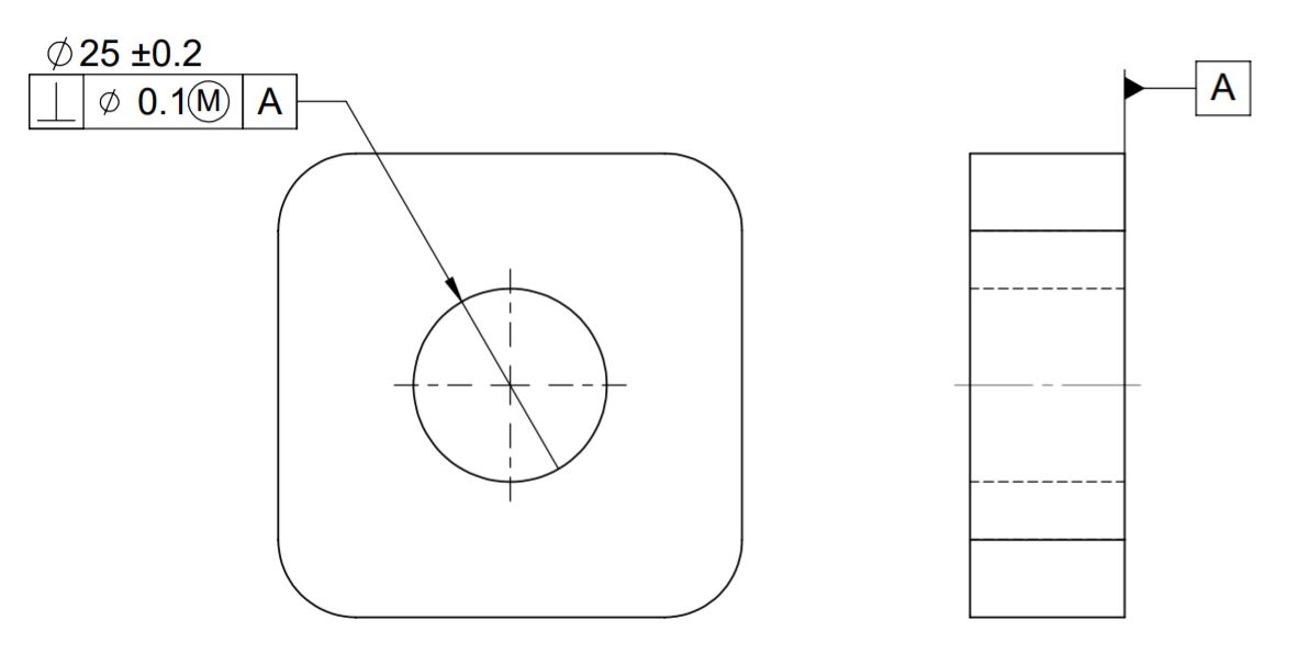
As shown in the above image, we use the diametric (Ø) symbol when applying perpendicularity to a circular feature (such as a pin, boss, or hole). This diametric symbol indicates a cylindrical boundary. All control points should lie within this boundary.
It has applications where we need to control the 90° angle between two axis or between axis & plane. LMC and MMC modifiers are used with perpendicularity to provide bonus tolerance. Click this link to know various GD&T symbols.
Perpendicularity Tolerance Zone
Perpendicularity tolerance does not control the angle between two surfaces, planes, lines, or features. It creates a tolerance zone where the controlled surface can lie.
In other words, Irrespective of controlled surface length, controlled surfaces can vary within gd&t perpendicularity limits.
When applied to an Surface
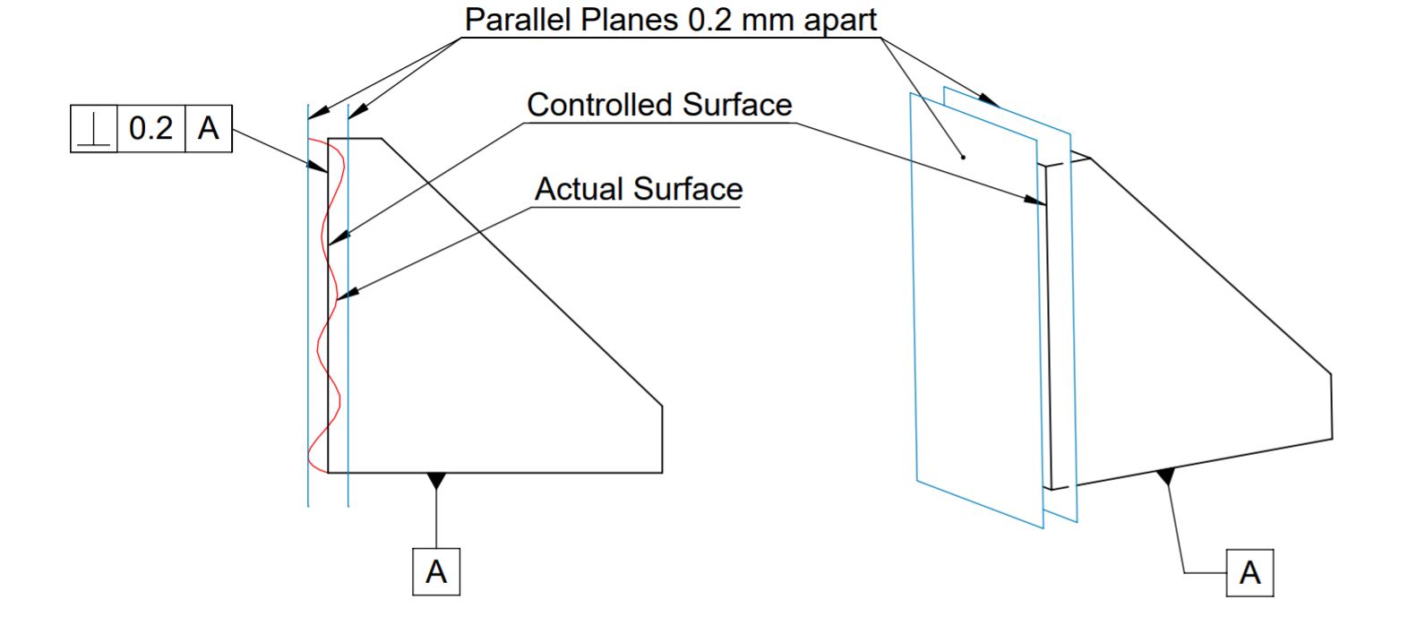
When we apply perpendicularity over the surface, the tolerance zone will be two parallel surfaces, planes, or lines perpendicular to the datum plane. All points on the controlled surfaces should lie within these limits.
When applied to an Axis
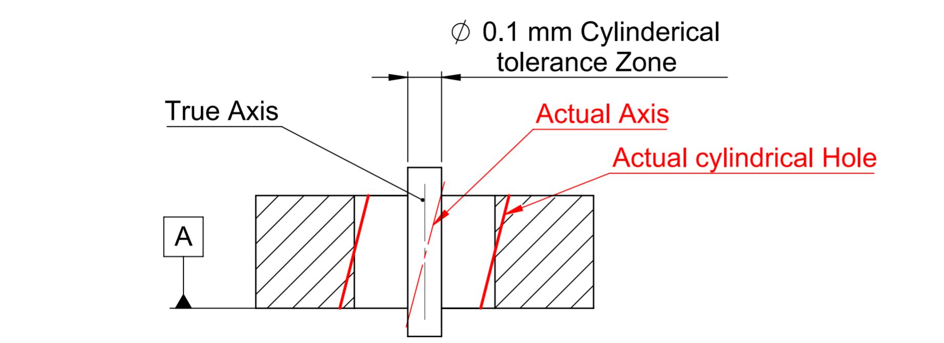
Whereas when applied to an axis. The tolerance zone will be a cylinder boundary around the true axis. All points of the axis of the controlled feature must lie within this cylindrical boundary.
How to measure GD&T Perpendicularity Tolerance?
When applied to an Surface
You can measure perpendicularity tolerance in the following ways when applying it to the surface:
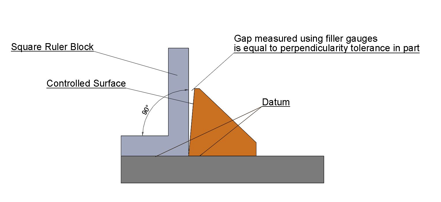
- Square Ruler Block and Surface Gauge.
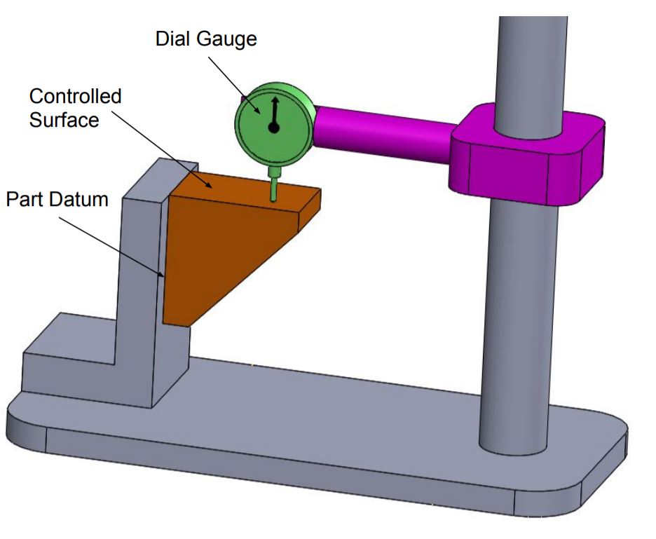
- Dial Gauge
- CMM or VMM machine.
When applied to an Axis
Go and No-go gauges are the best and easiest way to measure the perpendicularity of a hole or pin. For example, if the hole diameter is 10±0.5mm with 0.1 mm perpendicularity tolerance at MMC. Therefore (10-0.5-0.1 = 9.4 mm) diameter pin can be used as a go-gauge for that hole measurement.
We will keep adding more information on perpendicularity tolerance in gd&t. Add your comments, suggestions, or questions on Geometric Dimension and Control Tolerance in the comment box. Click this link to know various GD&T Symbols.
Add a Comment