Parallelism tolerance in gd&t is a type of orientation control tolerance that controls the parallelism of two lines, surfaces, or axis. It does not control the angle of the referenced feature. But it creates a tolerance zone of two parallel planes where all points of the feature must lie.
Don’t miss this article on the basics of “Geometric Dimension and Tolerance”.
Representation of Parallelism in GD&T
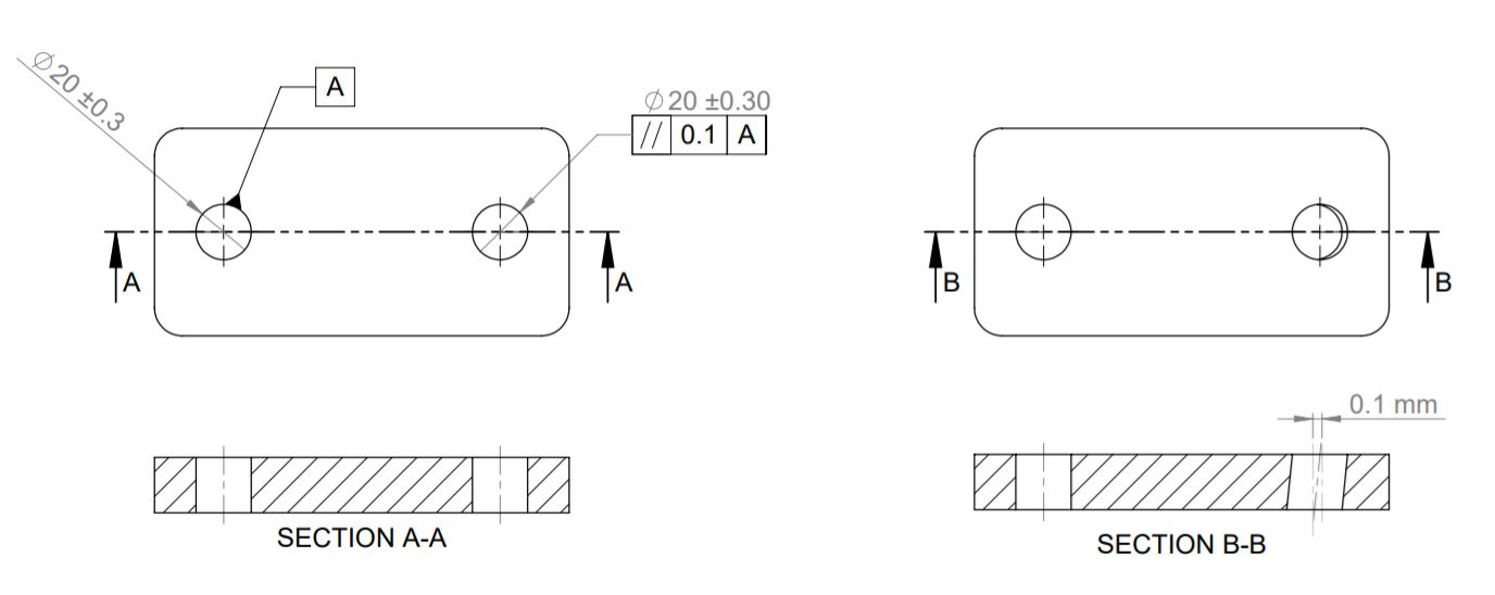
Parallelism in gd&t is represented by two parallel lines at an angle with mandatory datum surface, axis, or plane. We can also use MMC and LMC modifiers to provide bonus tolerance.
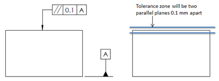
Tolerance Zone
We can apply parallelism in gd&t to the surface or an axis. When we apply it to a surface, it controls the parallelism between two planes. Whereas when we apply it to an axis, it controls the parallelelism of an axis is w.r.t. the reference plane.
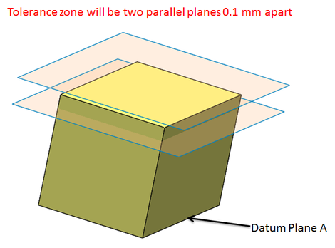
Parallelism Tolerance creates a tolerance zone of two parallel planes parallel to the datum feature or surface. All points on the controlled surface must lie within these parallel planes.
Applications of Parallelism Tolerance
Parallelism in gd&t ensures two surfaces are synchronized, and a constant distance between them is maintained. It also avoids taper in any slot or cylindrical hole. When applied to the axis of a hole, parallelism tolerance ensures hole orientation in defined constraints.
Application Example
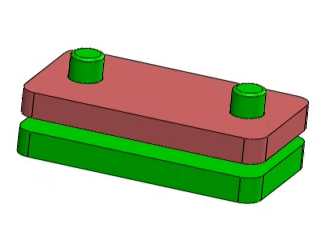
As shown above, if the requirement is to move a block inside two pins. To ensure the block is not struck during movement. We can apply parallelism tolerance at the axis.
Measurement of Parallelism Tolerance
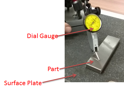
As shown above, to measure parallelism, we need to constraint the part against the datum plane and move the dial gauge across the controlled surface. Variation in dial gauge reading determines the parallelism tolerance in that part w.r.t. the datum plane.
I will keep adding more information on gd&t parallelism. Add your suggestions, comments, or questions on geometric dimension and control tolerance in the comment box. Click this link to know various GD&T symbols.
Add a Comment