It is not possible to manufacture 100% accurate parts during manufacturing. Therefore Limits, fit, and various types of tolerance are used in part dimensions to provide flexibility to the manufacturer. We decide part tolerances considering it has no impact on the part assembly and function.
During manufacturing, manufacturers always try to manufacture parts on the basic or nominal size, while ensuring it should not go beyond the tolerance limits. In this way, we cab reduce rate of part rejection and overall part manufacturing cost. This article covers various types of tolerance, limits, and fit in engineering. We suggest you also read this article on go no-go gauge.
Terminology used in Limit Fit and Tolerance
The following terms and definitions are widely used and very important to understand Limits, Fit, and tolerance in mechanical engineering.
Basic or Nominal Size
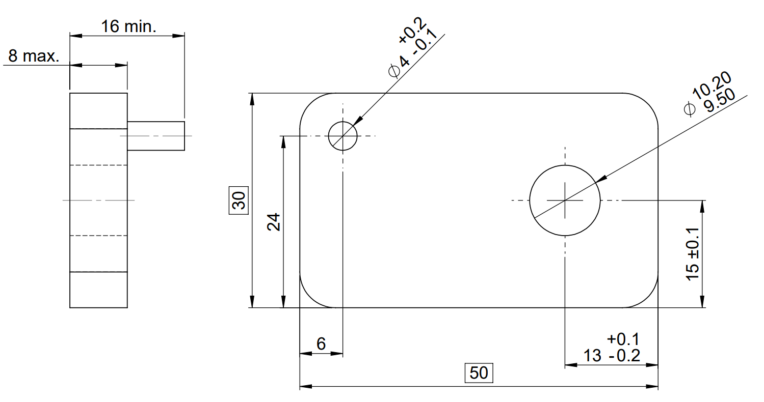
A part basic size is theoretical exact-size from where we define limits of size. In the above example shaft’s basic size is 4 mm.
Actual Size
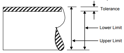
A part feature actual size is actual measured size. A part’s actual size should always lie within dimension tolerance limits (Upper and lower limits)
In the above example, the shaft’s actual size (diameter) is 4.3mm, if its measured diameter is 4.3 mm. But the quality team will reject the part because the shaft’s actual diameter is not within tolerance limits (3.9 to 4.2mm).
Maximum Material Condition (MMC)
At MMC or Maximum Material Condition, a part feature contains the maximum amount of material. In other words, maximum shaft diameter and minimum hole diameter are Maximum Material Conditions for a shaft and hole.
In the above example:
Maximum Material Condition for Hole = 9.5 mm
Maximum Material Condition for Shaft =4.2 mm
Least Material Condition (MMC)
At LMC or Least Material Condition, a part feature contain minimum amount of material. It is opposite to MMC. In other words, minumum shaft diameter and maximum hole diameter are Least Material Conditions for a shaft and hole.
In the above example
Least Material Condition for hole = 10.2 mm
Least Material Condition for shaft = 3.9 mm
Maximum Clearance
Maximum clearance is the maximum space available between hole and shaft or between two assembled parts.
For shaft-hole system
Max. Clearance = LMC (hole) – LMC (shaft).
Allowance
Allowance is the minimum space available between the hole and the shaft. In other words, allowance is minimum clearance between two parts.
Allowance (Min. Clearance) = MMC (hole) – MMC (shaft)
Limits of Size
The Limit of size is extreme permissible sizes for a feature or dimension of a part according to the given tolerance. Actual part dimension must lie within these limits.
As shown in the above example, the shaft’s basic size is 4 mm, and its upper and lower tolerances are +0.2 mm and -0.1 mm. Therefore shaft limits of the size will be:
Upper limit = 4.2 mm
Lower Limit = 3.9 mm.
Engineering Tolerance
As per ASME, Tolerance in engineering is the total amount a specific dimension is permitted to vary from basic value.
For example, If a given dimension is 25± 0.5. Its upper and lower tolerance value is 0.5 mm. Tolerance stack-up analysis ensures parts assembly even in the worst conditions.
Why do engineers need tolerance on mating parts?
Production of closely mating parts without tolerances is economically unfeasible. It increases the rejection rate and part manufacturing cost. Therefore engineering tolerances in part drawings are used for the following purposes.
- Provide flexibility to the manufacturer.
- Ensures smooth Product assembly even if parts are at an extreme tolerance limit.
- Reduce part rejection rate
- Interchangeability of manufactured parts.
Types of Tolerance
- Linear Tolerance
- Unilateral Tolerance
- Bilateral Tolerance
- Limit Dimensions
- Geometric Tolerance
- Form Control
- Profile Control
- Orientation Control
- Location Control
- Runout
1. Linear Tolerance
Linear tolerances are used to control the location and size of a feature independently or relative to another feature. In the above example, the position and size of a hole are controlled using a linear tolerance. Following three types of linear tolerances are widely used in engineering drawings.
- Unilateral Tolerance
- Bilateral Tolerance
- Limit Dimensions
Unilateral Tolerance
A unilateral tolerance is a type of tolerance where feature dimensions can vary only on one side of the basic size. In other words, tolerance lies only on one side of the basic dimension.
For example, if a hole’s basic size is 20 mm, and its value can vary from 19.85 mm to 20 mm. This type of tolerance is known as unilateral tolerance.
Unilateral Tolerances are used to define tolerances in precision fits parts. They are also easy to control in machining parts because operator can machine a shaft at upper limit and hole at lower limit. In this way, even after machining operator has flexibility to correct the machining part.
Bilateral Tolerance
In bilateral types of tolerance, feature dimensions can vary on both sides of the basic size. In other words, the tolerance limit lies on both sides of the basic dimension.
For example, if the hole’s basic size is 20 mm, its value can vary from 19.8 mm to 20.1 mm. This type of tolerance is known as Bilateral tolerance.
Manufacturer recommend bilateral tolerance system for high volume production parts. In this system, the operator always targets the basic size. These types of tolerance are widely used in engineering drawings.
Limit Dimensions
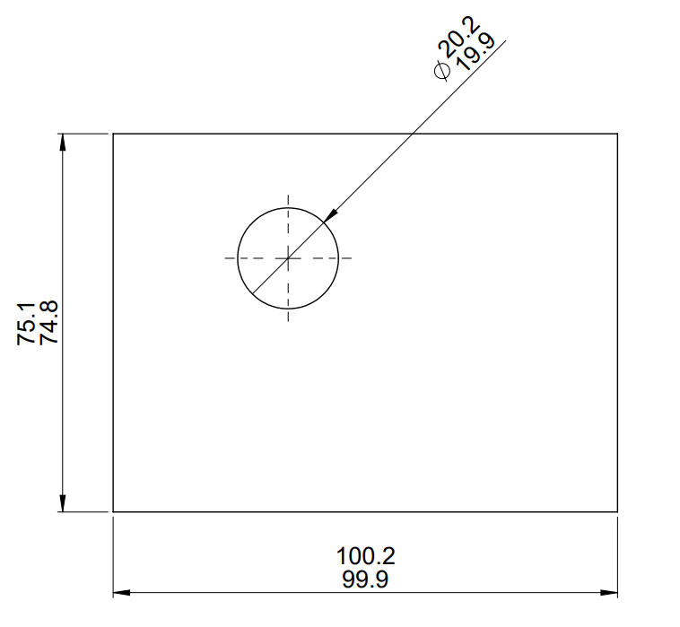
In Limit dimension linear tolerance, we define feature or part dimension upper and lower limits. It does not require the basic dimension. For example, We can define upper limit (20.2 mm) and lower limit (19.9 mm) for a hole to control its size.
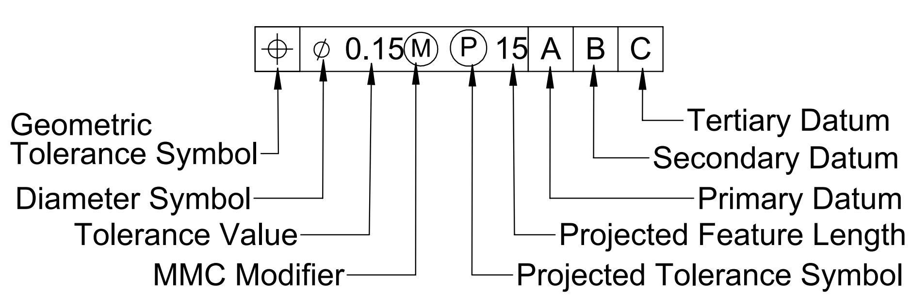
2. Geometric Tolerance
Geometric dimension and tolerance ( GD&T ) is a system to define nominal and allowable variations in the geometry of a part, component, or assembly. We use GD&T symbols along with linear tolerance. ASME Y14.5-2009 standard has defined GD&T tolerances in detail.
Linear Tolerancing has limitations in defining a part geometry in engineering drawing. Therefore we use geometric dimension and tolerance to define part geometry in engineering drawing.
GD&T has an advantage of a larger tolerance zone compared to linear tolerances. A larger tolerance zone reduces part rejection rate and manufacturing cost.
Engineering Fits
Engineering Fits are used to achieve the required type of assembly in between mating parts. They define the clearance between two mating parts. In other words, the required type of fit on mating parts, drives the dimensional tolerance on mating parts.
Types of Fits
Engineering Fits are classified into the following three types.
- Clearance Fit
- Interference Fit
- Transition Fit
Clearance Fit
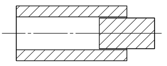
In clearance fit, the size of the hole is always larger than the size of the shaft. Therefore It ensures a clearance between mating parts. Clearance fit has a positive allowance. Following are the examples of clearance fit:
- Door hinges
- Shaft sliding inside a bearing
- Bearing inside ceiling fan
- Electrical switch and board etc.
Interference (Force/ Shrink) Fit
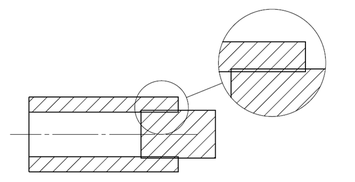
In Interference fit, the size of the shaft is always larger than the size of the hole. Therefore it ensures interference between mating parts. Interference fit has a negative allowance. Examples of interference fit Include:
- Press-fit inserts in plastic parts.
- Axle and bearing assembly etc.
Transition Fit
A transition fit can be a clearance fit or an interference fit. Therefore In transition fit, the shaft can be larger or smaller than the hole in a mating part. Transition fit is a compromise between clearance and interference fits.
Transition fit has overlapping tolerance zones of the hole and shaft. Therefore they are used where accurate feature location is critical to the product. But a small amount of clearance or interference is permissible.
Systems of Fit
The Basic hole system and basic shaft system are used to ensure the required fit between mating parts. We select the type of fit system according to standard parts in an assembly and manufacturing process.
Basic Hole System
In the basic hole system, the size of the hole is kept constant, and shaft size is varied to obtain the required fit.
For example, We consider the minimum hole diameter as the basic hole size. We calculate the tolerance and allowance in the mating part from basic hole size .
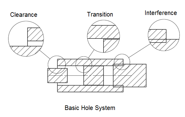
A basic hole system is more popular because we use standard drills, boring tools, and reamers to create holes in a part. Afterward, we control the shaft size using machining operations such as turning and grinding.
As a result, when we use a basic hole system, We can reduce the shaft size easily.
Basic Shaft System
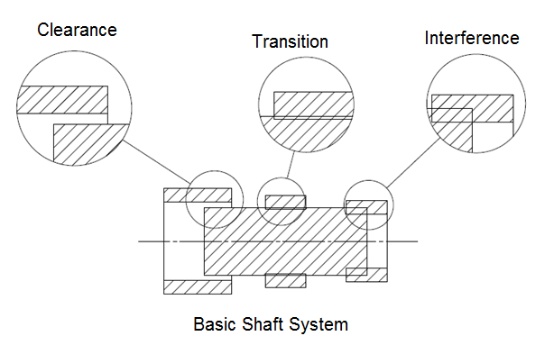
In the basic shaft system, the diameter of the shaft is kept constant and we modify the hole size to obtain the required fit.
For example, we consider the largest shaft diameter as the basic diameter in the basic shaft system. Afterward, we calculate part tolerance and allownces from basic shaft diameter. Manufacturer recommend the basic shaft system if standard-size shafts are available.
Commonly Asked Questions and Answers on Limit Fit and Type of Tolerance
Basic Size = 10 mm
MMC = 9.5 mm
LMC = 10.5 mm
Basic Size = 10 mm
MMC = 10.5 mm
LMC = 9.5 mm
Size of the Shaft = 9 ± 0.5 mm
Size of the Hole = 10 ± 0.5 mm
Maximum Clearance = LMC (hole) – LMC (shaft)
= 10.5-8.5 = 2 mm
Allowance = MMC (hole) – MMC (shaft)
= 9.5-9.5 = 0
Upper Limit = 12.2
Lower Limit = 11.8
It will be transition fit. Because interference or clearance may occur during assembly. To calculate we need to calculate the clearance or allowance between shaft and Hole.
Maximum Clearance = LMC (hole) – LMC (shaft)
= 30.2-28.8 = 0.4 mm
Allowance = MMC (hole) – MMC (shaft)
= 29.6-30.2 = -0.6 (-ve value indicates interference)
Since with interference and clearance may occur during assembly. This is a type of transition fit.
To sum up, Engineering tolerance is a very important and critical part of product design. Products can not be manufactured without tolerances. Tolerance stackup calculator is used to define tolerance value.
We will keep updating more details on limits fit and tolerance. Please add your comments, suggestions or questions in the comment box.
I need topics which are covered full mechanical design and product design and drafting
Hello,
When using a thread No/Go ring gauge , how many turns into the gauge to failure?
Thank-you
Todd
Excellent for learning