What is Circular Runout in GD&T?
Circular Runout tolerance in GD&T controls the total variation in a circular feature when the part rotates about the true datum axis.
Circularity calculates the roundness of a feature irrespective of datum, whereas runout determines the offset in an axis of a round feature w.r.t. the datum feature. Don’t miss this article on the basics of Geometric Dimension and Tolerance.
Circular Runout Representation in Engineering Drawing
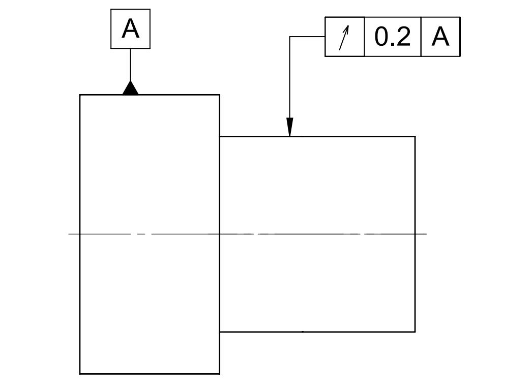
As shown, we can apply runout tolerance to circular and tapered cross-sectional surfaces w.r.t. a datum surface or an axis. LMC and MMC modifiers are not applicable with runout tolerance.
Tolerance Zone
Runout creates a 2-dimensional circular tolerance zone. All points of the controlled surface must lie within two circular lines when the part rotates about the datum feature. And these two lines should lie at a distance equal to the tolerance value and on the plane perpendicular to the axis of the control feature.
Product designers should decide how many points the manufacturer should control in the runout tolerance. Compared to total runout, We can measure the circular runout at various sections in the control surface.
Applications
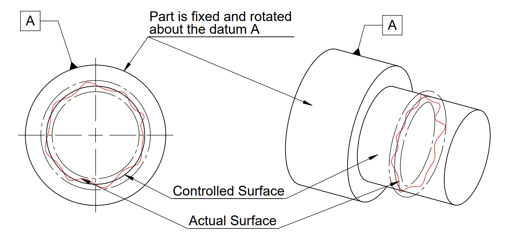
Runout or Circular Runout measures both concentricity and circularity of round features. It can also measure perpendicularity if the secondary datum is a plane perpendicular to the primary datum axis.
We can apply circular runout gd&t tolerance to rotating parts such as drill bits, shafts, vehicle axles, engine transmission parts, etc.
How to Measure Runout Tolerance?
As shown in the below image, we can measure runout tolerance using a height gauge, surface plate, and part rotating arrangement such as v-block or rotating chuck.
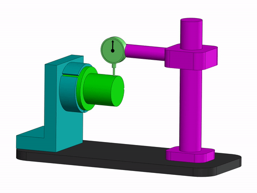
Firstly, we need to fix the part at the datum points and position the dial gauge at the highest point on the control surface.
Afterward, we need to rotate the part about the datum axis to measure the variation in a surface at different planes. Total variation in the control surface should not be more than the runout tolerance for the defining feature.
We will keep adding more information on circular runout in gd&t. Add your comments, suggestions or questions, on Geometric Dimension and Control Tolerance in the comment box.
Add a Comment