What is Angularity Tolerance in GD&T?
Angularity tolerance in GD&T controls the orientation of one feature or surface at an angle w.r.t. the datum plane. It ensures the variation in the control surface w.r.t. the True Surface is within limits.
For example, When we reference a feature to another feature at an angle of 30° with an angularity tolerance of 0.2. The controlled surface may vary 0.2 mm from the True Surface. Don’t miss this article on the basics of Geometric Dimension and Tolerance.
Angularity Tolerance Representation
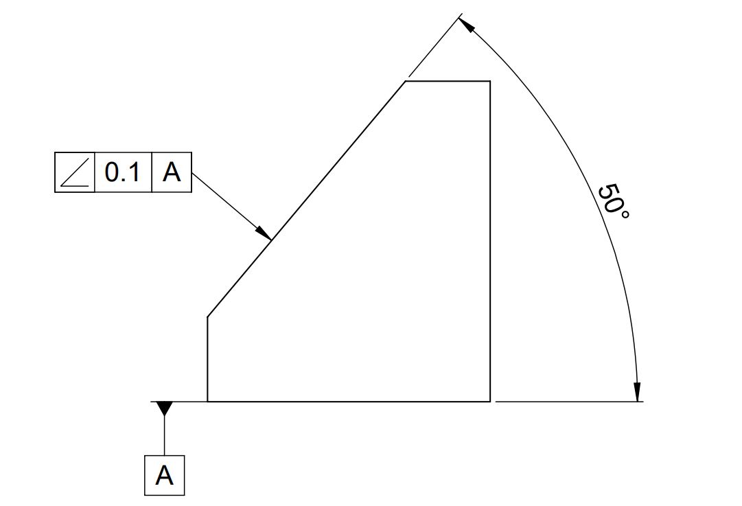
As shown above, we can apply GD&T Angularity to a surface or line to control its orientation w.r.t. datum plane/surface. It ensures the angle between the datum plane and line/surfaces is within limits.
LMC and MMC modifiers are used with angularity tolerance to provide bonus tolerance. It is very difficult to measure angularity when applied to an axis or with the maximum material condition. Click this link to know various GD&T Symbols.
Tolerance Zone
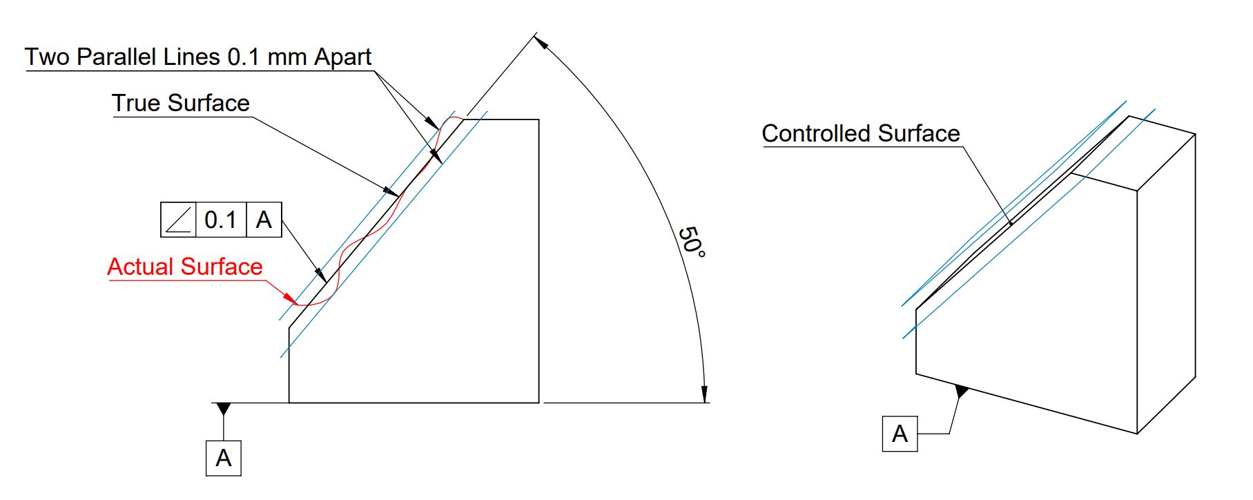
Angularity tolerance does not control the angle between two surfaces, planes, lines, or features. It creates a tolerance zone where all points of the control surface can lie.
When we apply angularity over a surface, the tolerance zone will be two parallel surfaces, planes, or lines from the actual controlled surface. All points on the controlled surfaces should lie within these limits.
How to Measure GD&T Angularity?
We can use the following methods to measure angularity tolerance in GD&T.
- CMM or Co-ordinate Measuring Machines
- Dial gauge, surface plate, angle plate, and Sine bar.
Angularity measurement using Dial Gauge
The first step to measure variation is to ensure the controlled surface is parallel to the surface plate. We can make the surface parallel using a Sine bar or angle plate.
Now user moves the dial gauge over the controlled surface. Total variation in dial gauge reading shall be less than angularity tolerance.
We will keep adding more information on angularity tolerance in gd&t. Add your comments, suggestions, or questions on Geometric Dimension and Control Tolerance in the comment box.
Add a Comment