What is GD&T tolerances?
Geometric dimension and tolerance ( GD&T ) is a type of tolerance used along with linear tolerance to define nominal and allowable variations in the part geometry or an assembly.
ASME Y14.5-2009 standard has defined different types of GD&T symbols in detail. This series of articles on geometric dimension and control will help you in the following ways.
- Understanding GD&T basics.
- Part design inspection.
- Creating engineering drawings with GD&T tolerances.
Why do we use GD&T Tolerance in Engineering drawings?
it is necessary to communicate part design and assembly requirements to the manufacturer to ensure manufactured part quality. Linear tolerancing has limitations in defining a part geometry in engineering drawing.
Therefore Geometric dimension and tolerance are used to define part geometry in engineering drawing accurately. GD&T has an advantage of a larger tolerance zone compared to linear tolerances. A larger tolerance zone reduces part rejection rate and manufacturing cost.
Types of GD&T Tolerance
- Form Control
- Straightness
- Flatness
- Circularity
- Cylindricity
- Profile Control
- Profile of a Line Control
- Profile of a Surface Control
- Orientation Control
- Parallelism
- Perpendicularity
- Angularity
- Location Control
- Position
- Concentricity
- Symmetry
- Runout
- Circular Runout
- Total Runout
Form Control
Foam control is a type of geometric tolerance that controls the form of the feature of a part. Location and Orientation tolerances can also be used to control the foam of a feature. Datum reference is not used with form control geometric dimension and tolerance. Following four types of Form Control Tolerance are used in GD&T.
Straightness 
Straightness in GD&T is a type of foam control tolerance. It is used to control the line on a surface / feature or an axis. In other words straightness controls a condition where all elements of a surface or an axis lies in a straight line. Datum planes are not required to define straightness. Whereas LMC and MMC modifiers can be used to define straightness of an axis.
Staginess of a part can also be controlled using linear dimensions as well. But gd&t straightness is used to provide more flexibility to the manufacturer. For example, a feature linear dimension 60±0.1 mm is equivalent to 60±0.5 with 0.1 mm straightness. But here in the second case more flexibility is provided to the manufacturer in part size while keeping straightness tolerance constant.
Flatness 
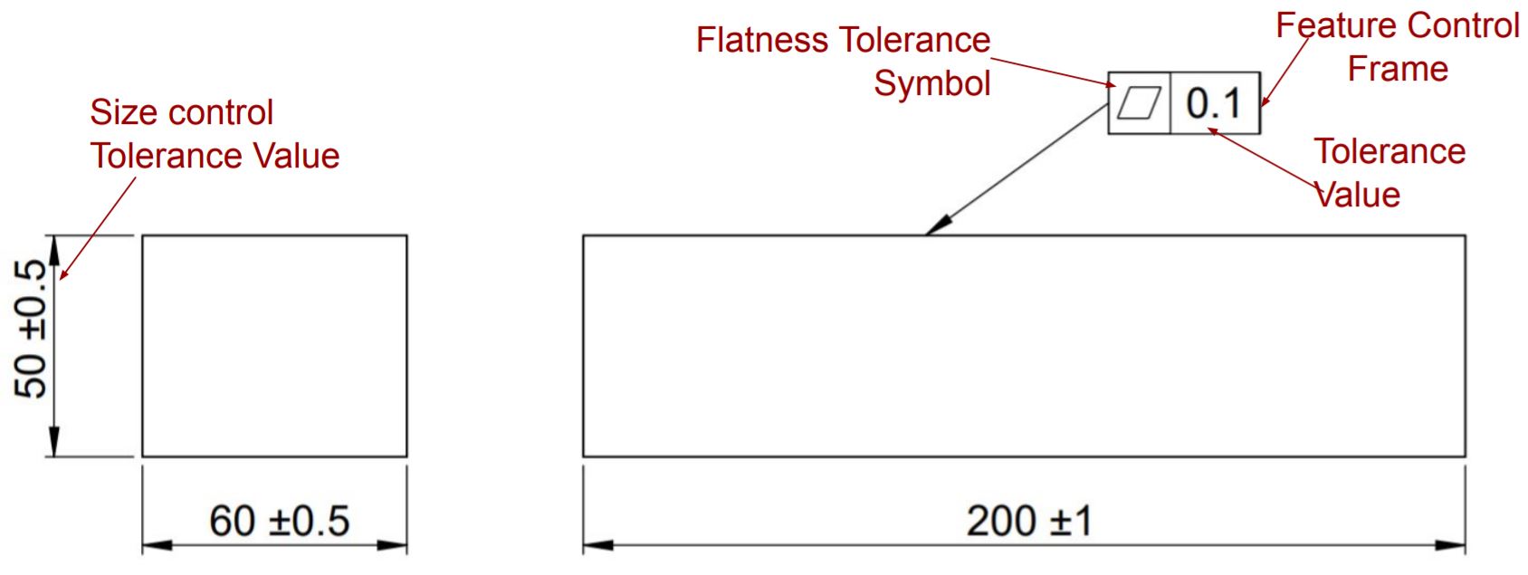
Flatness in gd&t is a type of foam control GD&T tolerance. It controls the variations in a flat surface, regardless of any datum feature. In this way it ensures the required surface is flat enough to perform the required function. Flatness tolerance value is always less than the dimensional tolerance associated with the part feature and LMC / MMC modifiers can be used to define flatness of a surface.
Flatness tolerance in gd&t defines the limit of waviness in a part. It is used to ensure a smooth contact between mating or moving parts. For example, flatness in Vernier caliper movable and fixed jaws is maintained to ensure it’s smooth operation. Without enough flatness, a movable jaw may struck inside the fixed jaw.
Circularity / Roundness 
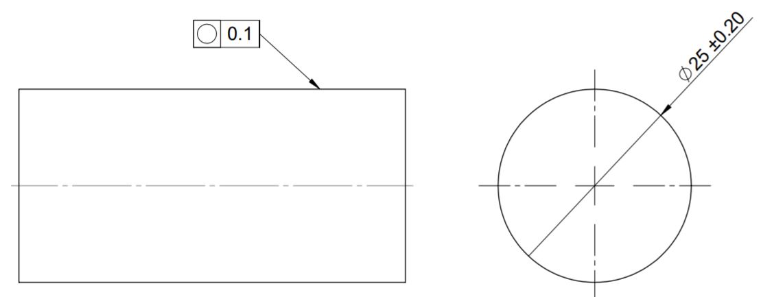
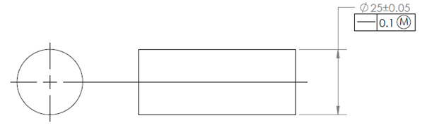
Manufacturing a perfect circular part may increase part manufacturing cost. Circularity tolerance is used to control irregularities in cylindrical, spherical or conical parts. It ensures all points on the plane of a circular feature are equidistant from the true central axis. In this way circularity in gd&t is used to control the roundness of a circular feature.
Circularity tolerance creates a 2 dimensional tolerance zone independent of any datum feature. It’s value is always less than the linear tolerance of circle diameter. For example, for a circular feature with diameter 16±0.2 mm. Circularity tolerance value can not exceed ±0.2 mm.
Cylindricity 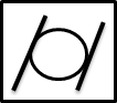
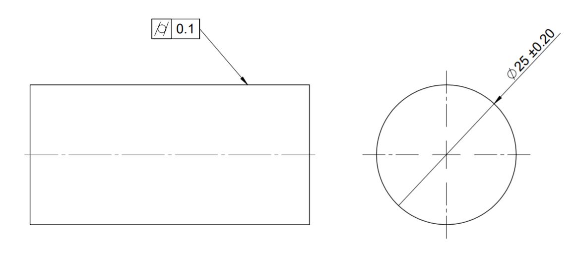
Cylindricity tolerance in gd&t is a type of foam control tolerance, that defines the allowable deviation in a feature from actual true cylinders. It controls the circularity and surface straightness of a controlled feature in a part. In this way, cylindricity controls a condition where all points on the surface of revolution are at that same distance from the actual central axis.
Cylindricity tolerance in gd&t creates a 3-dimensional tolerance zone independent of any datum feature. It ensures that the feature of a part is round and straight enough along its axis.
Profile Control
Profile control GD&T tolerance defines a uniform boundary around a surface. All points of the controlled surface must lie within a defined boundary. Profile Control Tolerance controls a feature form, size, orientation and location simultaneously. Following two types of profile control tolerances are used.
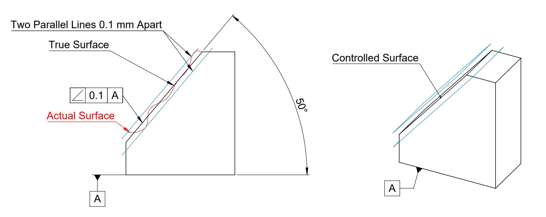
Profile Of a Line Control 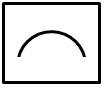
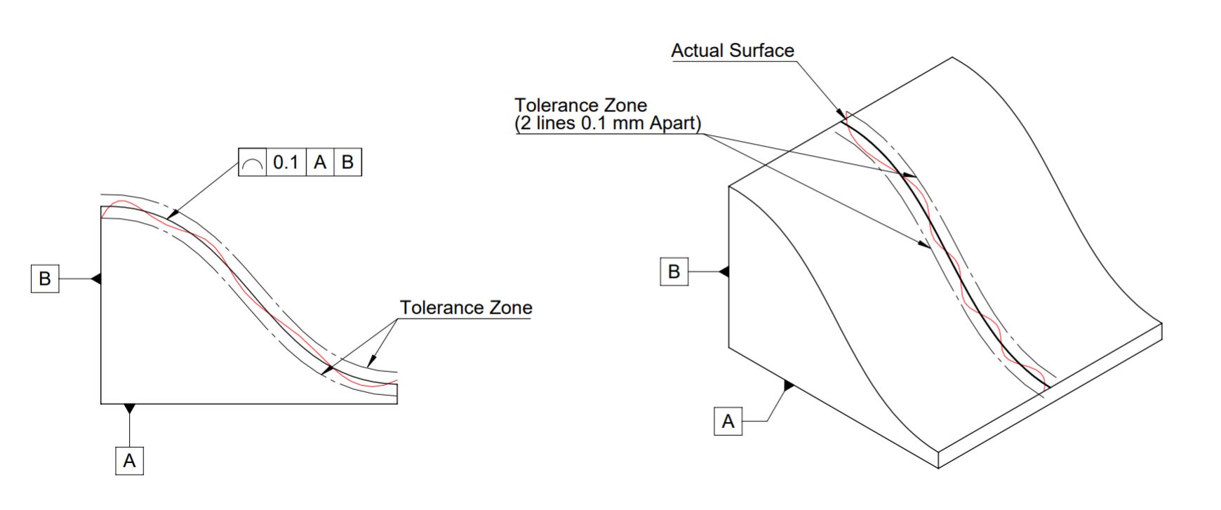
Profile of a line control tolerance in gd&t is a type of profile control tolerance, that controls the size, orientation, location and form of a feature simultaneously. When applied to a surface It creates a 2-dimensional bilateral tolerance zone of two parallel curves around the true surface or feature profile to be controlled. .
GD&T Profile of line control can be used with or without any datum plane and all-around. But MMC and LMC modifiers are not applicable with it.
Profile Of a Surface Control 
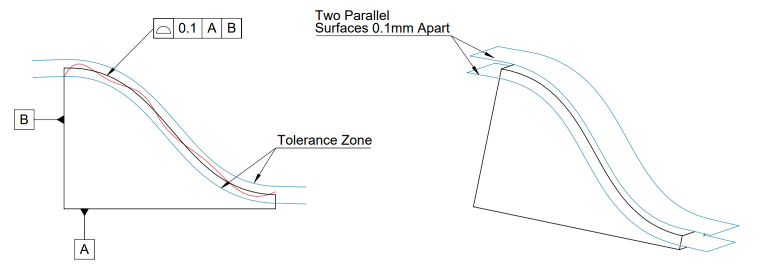
Profile of a surface control tolerance in gd&t is a type of profile control tolerance. It creates a 3D tolerance zone of two surfaces parallel to the true controlled surface and controls the size, orientation, location and form of a feature simultaneously. When applied to a surface, it controls the allowable variation in a surface from true surface.
GD&T Profile of surface control can be used with or without datum plane and all-around. But MMC and LMC modifiers are not applicable with it.
Orientation Control
Orientation Control type of GD&T tolerance controls the orientation of the part feature with respect to another feature or datum. Following three types of orientation control tolerances are used in GD&T.
Parallelism 
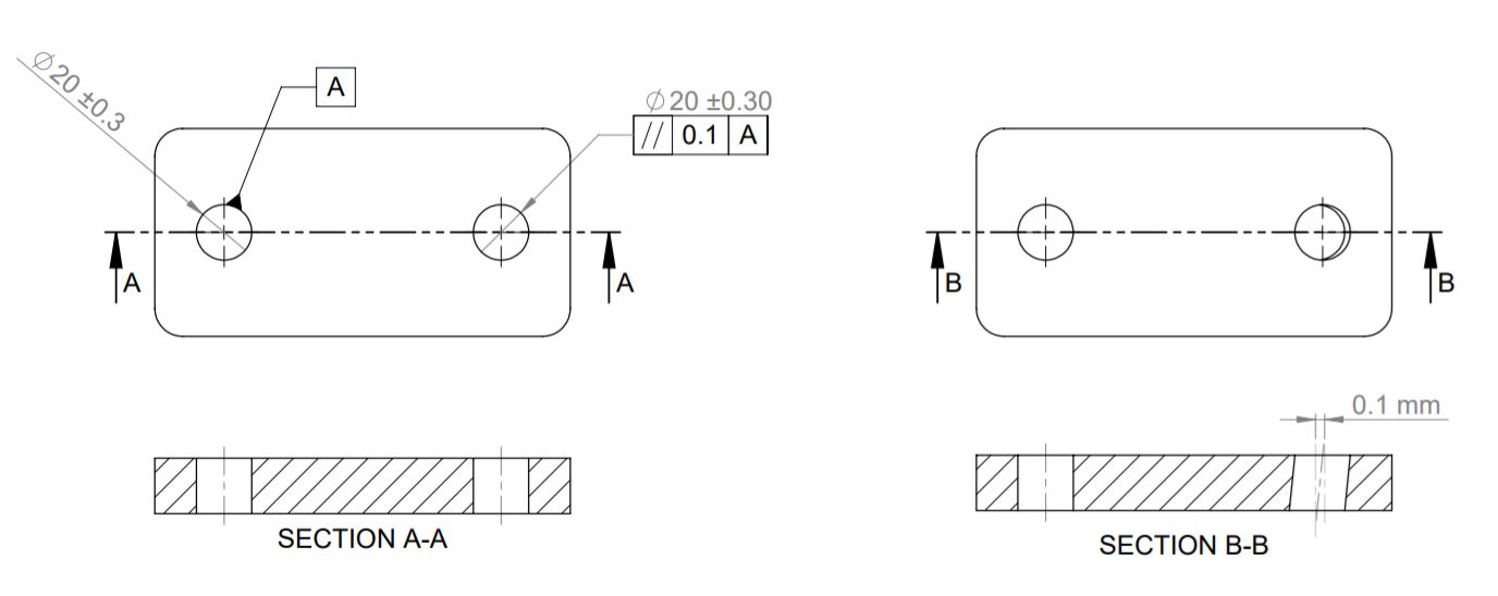
Parallelism tolerance in gd&t is a type of orientation control tolerance. It controls the parallelism of two lines, surfaces or axis. It does not control the angle of the referenced feature. But it creates a tolerance zone of two parallel planes where all points of the feature must lie.
Parallelism in gd&t is represented by two parallel lines at an angle with mandatory datum surface / axis / plane. MMC and LMC modifiers can also be used to provide bonus tolerance.
Perpendicularity 
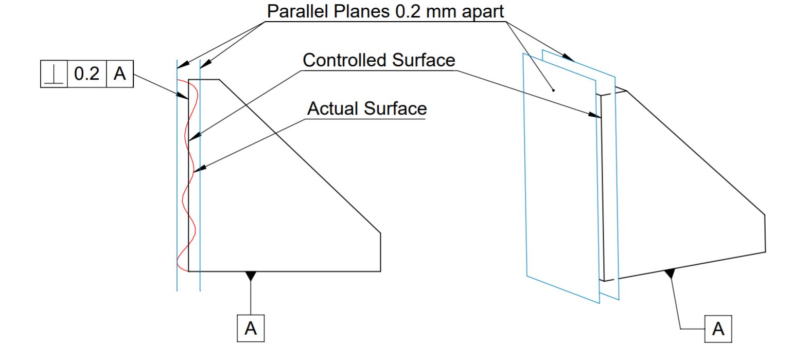
Perpendicularity tolerance in GD&T is used to control perpendicularity of a surface feature or an axis with respect to the datum plane. When applied to a surface, it controls how much surface can vary from perfect right angle (90º) w.r.t. to datum plane or surface and the tolerance zone will be two parallel surfaces, planes or lines perpendicular to the datum plane.
Whereas when applied to an axis, it controls how much the axis can vary from perfect right angle (90º) w.r.t. the datum axis or plane and the tolerance zone will be a cylinder boundary around a true axis.
Angularity 
Angularity tolerance in GD&T is used to control how one feature or surface is oriented at an angle with respect to the datum plane. It does not control the angle of a surface, Angularity controls how much a surface can vary from a true surface at the basic angle from the datum plane or surface. For example, When a feature is referenced to another feature at an angle 30° with angularity tolerance 0.2. It means the controlled surface may vary 0.2 mm from the true surface.
GD&T Angularity can be applied to a surface or line to control its orientation w.r.t. a datum plane or a surface. But angularity is very rarely used with axis or MMC. Because it is very difficult to measure angularity when applied to an axis or with maximum material condition.
Location Control
Location control types of Geometric Tolerance defines the deviation of a feature from the actual location. Position, Concentricity and symmetry are the three types of location control tolerance. Concentricity and symmetry controls the center distance of a feature whereas position tolerance controls coaxiality of a features.
Position Tolerance 
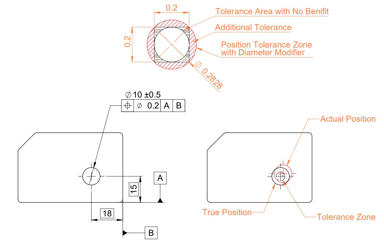
GD&T Position tolerance controls the variation in the location of a feature (hole, slot or pin) from its true position. For example, When a hole true position is defined. Position control in gd&t controls the allowable deviation in hole location from it’s true position.
Following points are considered while specifying position control in engineering Drawing:
- Two or three datum planes are required to specify position control.
- Material Condition (MMC and LMC), Projected Tolerance, Tangent Planes can be used.
- Generally diameter symbols is used to make circular or cylindrical tolerance zones.
Concentricity 
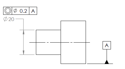
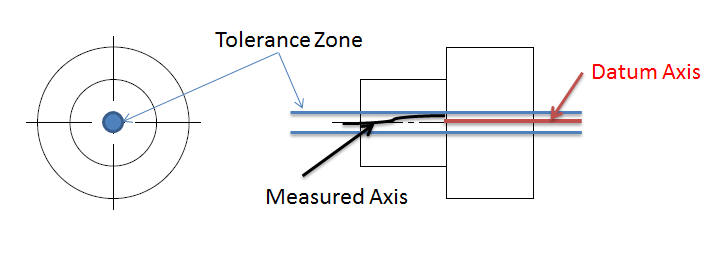
Concentricity tolerance in GD&T controls the central axis of a cylinder or sphere with respect to the datum plane or an axis. It creates a 3-dimensional cylindrical tolerance zone around the datum axis. All central points of the circular feature must lie in this tolerance zone. For example, in transmission gears, Concentricity is used to ensure gear axis are concentric to each other. Following points should be considered while specifying concentricity tolerance:
- Datum planes, surfaces or axis are required to define concentric tolerance.
- LMC and MMC modifiers are not applicable with concentric tolerance.
Symmetry 
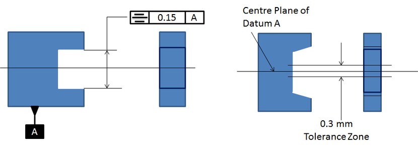
Symmetry tolerance in GD&T creates a 3-dimensional geometric tolerance zone with respect to the datum plane. It controls how much the points between two features may deviate from a specified center plane or axis. It can only be applied to non circular features.
Symmetry tolerance is similar to concentricity. But it controls rectangular features and involves two imaginary flat planes.
Runout
Runout in gd&t tolerance controls the variation in a feature when the part is rotated 360° around the datum axis. Following two types of runout control are used in geometric dimension and control.
Circular Runout 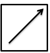
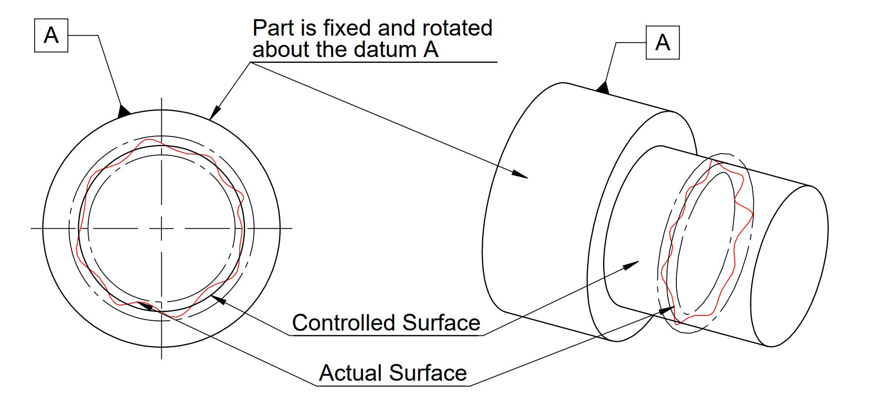
Circular Runout tolerance in GD&T is used to control the total variation in a circular feature when the part is rotated about the true datum axis. It is different from circularity because circularity calculates the roundness of any feature irrespective of any datum. Whereas runout determines the offset in an axis of a round feature with respect to datum feature.
LMC and MMC modifiers are not used with runout tolerance. Runout creates a 2 dimensional circular tolerance zone. All points of the controlled surface must lie within two circular lines when part is rotated about the datum feature.
Total Runout 
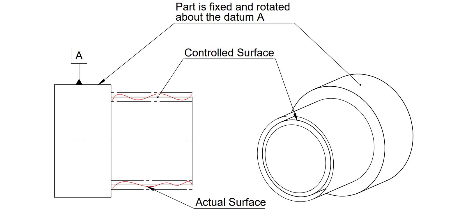
Similar to Circular runout, Total Runout tolerance in GD&T is used to control the variation in a feature when the part is rotated 360° about the datum axis. It is different from cylindricity because cylindricity calculates the roundness of any feature irrespective of any datum. Whereas total-runout determines the offset in the axis of a cylindrical feature with respect to datum feature. LMC and MMC modifiers are not used with Total runout tolerance.
Total-Runout tolerance creates a 3 dimensional cylindrical tolerance zone. All points of the controlled surface must lie within two cylindrical surfaces (at a distance equal to tolerance value) when the part is rotated about the datum feature.
To sum up, Geometric Dimension and tolerance (GD&T) has the advantage of communicating part design and assembly intent in engineering drawing. It also helps in increasing the tolerance zone as well. Tolerance stack up calculator can be used to calculate required tolerance.
We will keep Updating more details on GD&T Basics. Please add your Feedback on content, questions on GD&T Basics : Geometric Dimension and Control in the comment box.
I have a doubt related to tolerance which is show with symbol. These tolerances are in bilateral or unilateral. Bcz. Here is no sign. For identify. So please help me.
Tolerances shown with symbol is total tolerances. For example if flatness of 0.1 mm is given that means that surface can vary in 0.1mm in total while satisfying total feature tolerance.
Sir, how will act GD & T in plastic design and how to give GD & T for plastic parts in 2D.
Please help me.
how does profile of a line and profile of a surface associate to ANY datum?
It is in itself!
Its like constraining the part wrt datum plane/surface. It controls a feature profile wrt other plane or feature