We follow Sheet metal design guidelines to ensure the quality and manufacturability of sheet metal enclosures. As a result, you can deliver the product at a low cost and faster timeline. It is difficult to follow all sheet metal design guidelines for complex sheet metal parts.
Therefore exceptions can be there for complex sheet metal parts. But good practice is to test these exceptions before design release. In this article, we will discuss sheet metal design guidelines considering a press bending machine.
Sheet Metal Design Guidelines
You should consider the following points during the design of sheet metal parts for press bending.
Sheet Metal Material Selection
Sheetmetal is available in standard thickness. Manufacturer provides sheets thickness in gauge. But sheet metal parts design is done considering sheet thickness in mm.
Sheet metal material selection is a critical part of product design. It has an impact on the sheet metal part design as well. You can decide sheet thickness and select the material in the following ways.
- Simulation Studies
- Past Experience
- Reverse Engineer existing products
- Experimental Studies
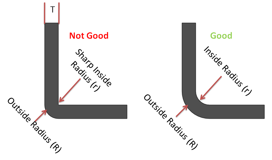
Minimum inside bend Radius for Sheet Metal Parts
Recommended inside bend radius for sheet metal parts should be equal to material thickness. For hard materials (Stainless steel, CRCA), an inside bend radius equal to 0.65 times of sheet thickness is also enough.
Sharp inside bend radius in sheetmetal parts can cause material flow problems in soft material and fracturing in hard material. It results in localized necking or fracture. Therefore sharp bend radius is not recommended in sheet metal parts.
The bend radius throughout the sheet metal part is kept constant. It has the advantage of using the same sheet metal bending tool during manufacturing.
Minimum Sheet Metal Bend Length Recommendations
The minimum recommended sheet metal flange bend length avoid cracks in the bending area. It shall be equal to three times of sheet thickness plus bend radius.
Minimum Sheet Metal Flange Bend Length = 3 x Sheet Thickness + Bend Radius
Sheet metal Hole Diameter Guidelines

Small-sized punches are more prone to failure during sheetmetal punching operation. Therefore for softer materials, the recommended minimum hole diameter is equal to sheet thickness. Whereas for harder materials recommended minimum hole diameter is equal to two times of sheet thickness.
Hole/Slot Distance from Bend Edge
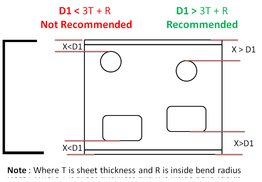
The minimum distance between hole/slot edge to bend edge avoid metal distortion, deformation, and fracturing. The recommended minimum distance between hole /slot edge to bend in sheet metal parts is three times the sheet thickness plus bend radius.
Center to Center Distance Between two Holes
The minimum center to center distance between two holes in sheet metal parts avoids metal distortion, deformation, and fracturing.
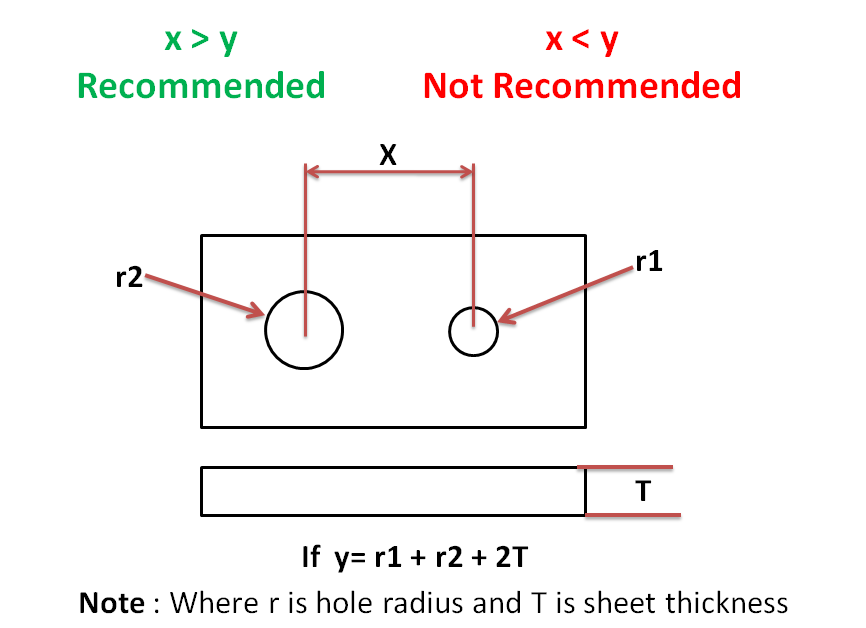
The recommended minimum distance between two hole centers in sheet metal design should be equal to the sum of hole radius plus two times the sheet thickness.
Recommended Distance = Radius of Hole1 + Radius of Hole2 + Sheet Thickness
Effect of Grain Direction in Sheet Metal Bending
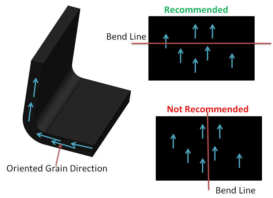
During sheet metal processing ( rolling operation), material grain arranges in the direction of rolling. The material grain rearranges when Sheetmetal is bent perpendicular to the rolling direction. That has a negligible impact on part strength. Whereas bending parallel to the rolling direction can lead to cracks because of destruction in grain structure.
Bend Relief in Sheet Metal Bend

Bend relief is provided at the end of the bending edge in sheet metal design to avoid any crack tearing in the corner. Recommended Bend Relief height is always more than two times of sheet thickness plus bend radius.
Extrude Hole Size and Position Guidelines
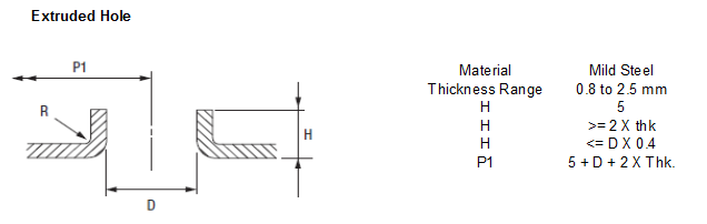
Creating an extruded hole using a punching process requires extreme pressure/Force. Extruded holes very close to the part edge can lead to sheet metal deformation or tearing. Therefore the minimum distance between the extruded hole to edge is maintained.
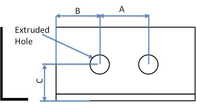
Extruded hole to part edge (B) = 3T + D/2
Center of extruded Holes (A) = (5 + Hole Dia + 2T)
Extruded Hole and bend edge (C) = 3T + R + D/2
Round Emboss Design Guidelines
Creating Emboss feature using sheet metal punching requires extreme pressure. Very close emboss to the part edge can lead to deformation in the sheet metal part.
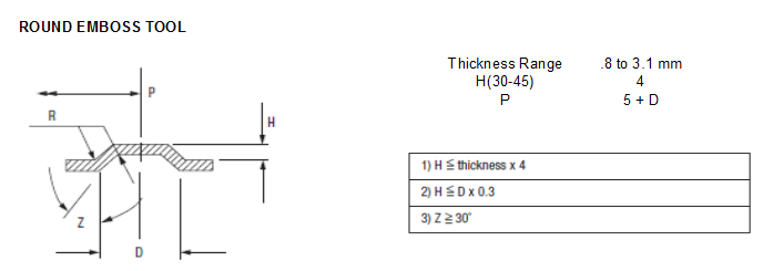
A – Distance From Emboss To part Edge = 3T + D/2
B- Distance Between Two Emboss = (5 + D)
C- Distance between Emboss and Sheet Metal bend = 3T + R + D/2
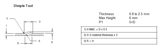
Dimple Feature Design in Sheet Metal Parts
Louver Feature Design in Sheet Metal
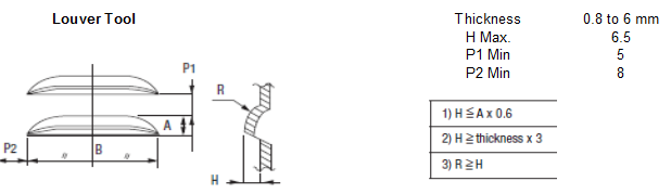
The minimum distance between the louver feature and bending edge is maintained to avoid metal deformation.
(P1) Distance Between Two lowers on Shorter Edge = 5 mm
(P2) Distance Between Two lowers on Longer Edge = 8 mm
Round Knockout Design Recommendation
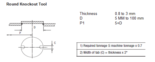
The minimum distance between the knockout feature and bending edge is maintained to avoid metal deformation.
(P1) Distance Between Two knockout = (5 + D) mm
To sum up, sheet metal design guidelines ensure good quality, reduced cost, and robust design sheetmetal parts. It is difficult to follow all design guidelines in the critical parts. Therefore exceptions can be there for complex features design. We suggest you read this article on electronics enclosure design. It will give you an overview of the complete enclosure design process.
We will keep adding more information on sheet metal design guidelines. Write to us if you need any support in sheet metal part design.
Good knowledge
Yes good information, please ping me in 7022195229,
I have some doubt regarding sheet metal design
Important information about sheet metal