Snap fit joints are the best and most cost-effective solutions to assemble plastic parts. We can join plastic products without screws or welding joints using snap-fit joints. This article will give you details on how to design snap-fit joints for injection-molded plastic parts?
What is Snap Fit Joint?
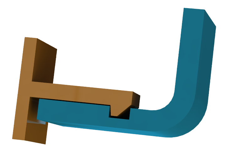
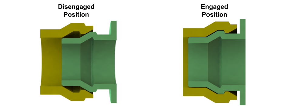
A snap-fit joint consists of a protrusion in a flex plastic wall and groove in the mating part. During part assembly, a force is applied to the flex part. This force deflects the flex part, and the cantilever snap protrusion goes inside the mating part groove.
Advantages of Snap Fit Joints
Plastic snap joints have the following advantages compared to other types of joints in plastic parts.
- Simple and reliable.
- Improved Aesthetics: The product looks clean because the fasteners are not visible from the outside.
- Reduced number of parts: Additional fastener such as a screw is not required.
- Product assembly cost reduces because snap joints are easy to assemble.
- Overall product cost reduces because snap joints do not require additional fasteners.
- Temporary joints: Disassembly of products with snap joints is possible without damaging the parts.
- Permanent Snap Joints are also feasible.
Disadvantages of Snap Fit Joints
Here are the disadvantages of using snaps to join plastic products:
- Undercuts are required to create a snap feature in plastic parts. These undercuts will increase the injection mold tool cost.
- You need to scrap part if even one snap gets damaged.
- You should follow snap design guidelines for easy assembly & disassembly of snap joints and avoid overstress in the snap feature.
- Snaps are not as strong as screws.
- A waterproof enclosure design with snap joints is a challenging task.
Types of Snap Fit Joints
Following three types of snap fit joints are widely used to join plastic parts.
- Cantilever Snap Joints
- Annular Snap Joint
- Torsion Snap Joints
1. Cantilever Snap Fit Joint
Most snap joints used to join plastic parts are cantilever snap joints. Cantilever snap joint one end is fixed, whereas the other end protrudes out. They work similarly to the cantilever beams.
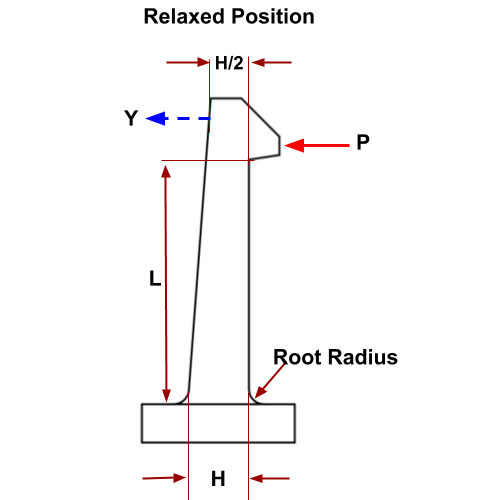
When we apply a force to the snap-joint, the flexible length deflects and catches in the depression of the mating part. During deflection, maximum stress acts at the root of the joint. We can calculate maximum root stress using classical beam bending theory.
Cantilever Snap Fit Joint Design
The entrance angle at the entry of the cantilever snap provides a smooth part assembly. The force required to engage the cantilever snap is directly proportional to the entry angle. Therefore it is always recommended to keep the minimum possible entry angle.
The cantilever snap exit angle at the stopping face ensures easy removal of the part. Recommended exit angle for removable cantilever snap is greater than 90° with the vertical wall. Whereas for recommended exit angle for non-removable cantilever snap is less than 90°.
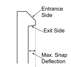
But if the cantilever snap entry and exit angle are equal, an equal amount of force will be required to engage and disengage the snap joint.
In real scenarios, Recommended entry and exit angle is less than 45° and 5°. It ensures that snaps are easy to enter but difficult to remove.
Maximum snap deflection is the deflection to engage the snap with the mating part without failure. Its value depends on snap cross-section area, snap length, and material maximum permissible strain. Consider the Factor of Safety during snap design calculations.
Cantilever Snap Fit Joint Calculations
As discussed above, a cantilever snap design works similar to a cantilever beam with a pointed load. We can use beam theory for snap design calculations to calculate the maximum snap deflection corresponding to allowable strain in the cantilever beam.
We can calculate cantilever snap assembly and disassembly force from maximum beam deflection and snap structure.
Cantilever Snap Deflection Calculations (For Uniform Cross Section)
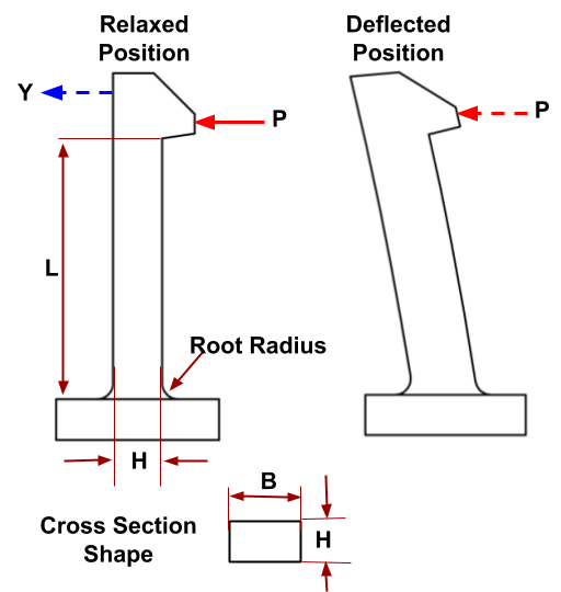
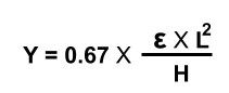
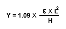
Maximum cantilever snap deflection in a uniform cross-section snap is calculated similarly to the deflection of a uniform cross-section beam.
According to Beam Theory
Where:
“Y”: Snap Deflection.
“ε”: maximum permissible strain for the plastic material.
“L”: Snap Length.
“b” : Cross section Width.
“H”: Snap Thickness.
“P”: Applied Force.
Cantilever Snap Deflection Calculations (For non-Uniform Cross Section)
Cantilever beam thickness is reduced gradually (up to 50%) from the root to the top of the cantilever snap to increase snap deflection or reduce stress on the cantilever snap.
Snap Mating Force Calculations
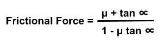
Mating or assembly force is the force required to engage the snap joint. Mathematically it is equal to the multiple of snap deflection force and frictional force.
Snap Mating Force = Deflection Force(P) x Frictional Force

Where
“E”: Flexural / Bending Modulus of the material.
∝: Entry angle
μ: coefficient of friction between materials.
Permissible Strain Values for Plastic Materials
Maximum permissible strain value is a property of a material. You can calculate maximum-permissible strain if the value of the young modulus of elasticity and maximum-permissible stress are available. This value is also available in the material datasheet. Read this article for more details on strain in mechanical.
| Maximum Permissible Strain Values For Reference | |
|---|---|
| Material | Acceptable Strain |
| Polycarbonate (PC) | ~ 4 to 8 % |
| ABS + PC | ~ 4 % |
| Glass Filled PC | ~ 2 to 2.2 % |
| ABS | ~ 6 to 7 % |
Cantilever Snap Calculator
2. Annular Snap Joint
The annular snap joint application is to join symmetrical round parts. Annular joints can be removable, permanent, or difficult to remove depending on the joint geometry. Complex plastic tooling is required to make parts with annular snap joints.
Common Problems in Snap Fit Joints
Following are the common problems faced during the snap design and product lifetime. We can solve these problems by designing plastic parts smartly.
Snap Deflection is not enough
We face the following two problems during snap design very frequently.
- Snap deflection or overlap is not enough.
- High strain in snap section.
We can solve the above problems in the following ways.
- Select plastic material with high permissible strain.
- Increase snap length.
- Reduce snap cross-section thickness.
Out of these options, changing material is not a good choice because limited material options are available, whereas increasing snap length impacts product size.
Therefore Reducing snap thickness gradually is a promising option because it will increase snap deflection and have no impact on snap structural integrity.
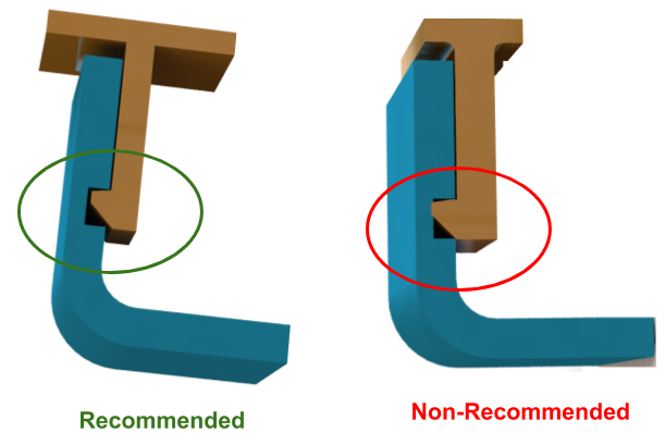
Stress Concentration
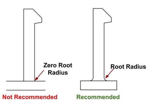
During snap engagement, maximum stress acts at the root of the snap joint. Therefore a generous root radius on the snap bottom is recommended to reduce stress concentration.
Stress Relaxation
During snap design, designers should ensure clearance between mating parts even in the worst conditions because it ensures the snap is always in a relaxation state.
We will keep updating this article on various types of snap joints. If you need any support in plastic parts snap designs or have any questions. You can write us in the comment box.
Root Radius–I think you have the wrong one recommended? you want the round, right?
Thanks for your valuable feedback. We accept this error. Now its corrected.
How to consider the tolerances in annular snap joints for permanent fit.
How to consider for clip round the tube type snapfit
Just a bit confused about the engagement force – you said its frictional force x deflection force, do you mean coefficient of friction*deflection force? How did you get the frictional force equation?
HERE YOU SAID TOTAL FORCE=FORCE TO DEFLECT THE SNAP + FRICTIONAL FORCE
BUT THE PREVIOUS ONE YOU SAID LIKE THAT ITS THE PRODUCT OF TWO
WHICH ONE IS CORRECT
Total force = snap force + friction force. Often we ignore friction force during engagement.
Please share calculated values
Can you please help me to explain what is the bending modulus of the material
One can consider lower value of elastic modulus as the bending modulus from the material data.
HERE YOU SAID TOTAL FORCE=FORCE TO DEFLECT THE SNAP + FRICTIONAL FORCE
BUT THE PREVIOUS ONE YOU SAID LIKE THAT ITS THE PRODUCT OF TWO
WHICH ONE IS CORRECT