Top GD&T Interview Questions and Answers for Mechanical Engineers

GD&T stands for Geometric Dimension and Control is a type of tolerance used to define the geometry of a component. It is extensively used by design engineers to define design intent for a part. In this article, we will discuss top GD&T interview questions and answers. Click this link!! for more details on GD&T.

Here are the top commonly asked GD&T interview questions with answers.

1. What is GD&T?

Geometric dimension and tolerance ( GD&T ) is a system to define nominal and allowable variations in part and assembly geometry. They are used along with linear toleranceASME Y14.5-2009 standard has defined GD&T symbols in detail.

2. Why do we require Geometric dimension and tolerance?

GD&T symbols are used to accurately define part geometry in engineering drawing. To ensure manufactured part quality. It is necessary to communicate design and assembly requirements in a drawing. But It is not possible to completely define part geometry using linear tolerance. 

Geometric dimension and tolerance have the advantage of a comparatively larger tolerance zone. Therefore part rejection rate and cost also decreases.

3. What are different types of GD&T Tolerances?

Here are the Five types of Geometric Tolerance and 14 symbols used to define a part design intent accurately.

  1. Form Control
    • Straightness
    • Flatness
    • Circularity
    • Cylindricity
  2. Profile Control
    • Profile of a Line Control
    • Profile of a Surface Control
  3. Orientation Control
    • Parallelism
    • Angularity
    • Perpendicularity
  4. Location
    • Position
    • Concentricity
    • Symmetry
  5. Runout
    • Circular Runout
    • Total Runout
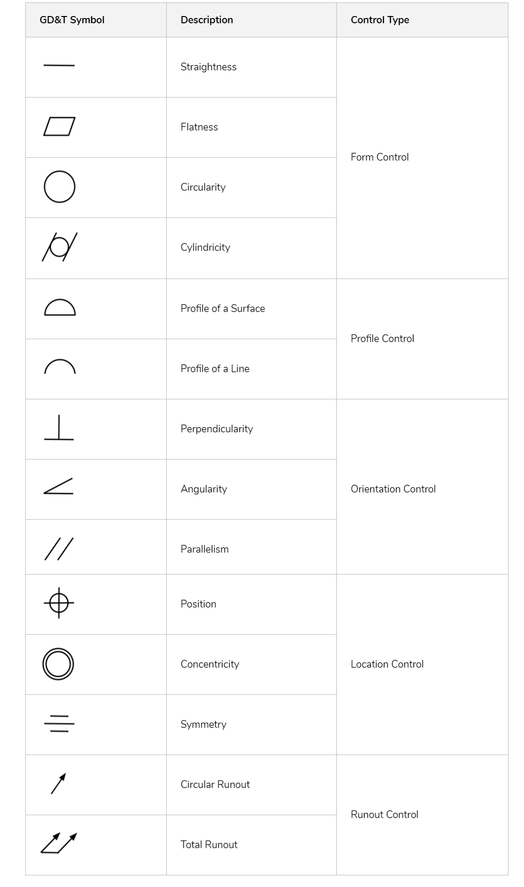
4. What are different symbols used in GD&T?

Here are the different symbols used in GD&T.

List of Geometric Dimension and T Symbols

5. What is the difference between straightness and Flatness?

Both Straightness and flatness are types of form control tolerances. Straightness controls a condition where all elements of a surface or an axis of a feature lies in a straight line. Whereas Flatness controls the variations in a flat surface, regardless of any datum feature.

6. What is the difference between Circularity and Cylindricity in GD & T?

Both Circularity and Cylindricity are a type of form control tolerance. Circularity is used to control the roundness of a circular feature in a two-dimensional tolerance zone. Whereas Cylindricity is used to control the roundness of a circular feature in a 3-dimensional tolerance zone. 

7. Why Profile control tolerances are used in GD & T?

Profile of a Surface Control Tolerance creates a uniform 3D boundary tolerance zone along full length and width of the surface.

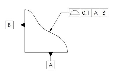
Profile of Line and Profile of Surface control tolerances are used to control the complex profile of a feature. For example, as shown above, part profile can not be controlled using linear dimensions.

8. Does perpendicularity and angularity control in GD & T controls the angle of a feature?
This image shows the tolerance zone created by gd&t perpendicularity tolerance on an axis.
Axis Perpendicularity Tolerance Zone

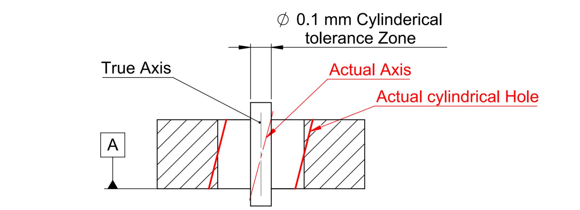
No, Perpendicularity and angularity control the deviation of a feature from required values. As shown above, hole axis can deviate by 0.1 mm from the original position.

9. What are different Modifiers are used in GD & T?

Here are the list of modifiers used in GD&T

GD&T SymbolDescription
Least Material Condition
Maximum Material Condition
Projected Tolerance Zone
Free State
Tanget Plate
Diameter
Radius
Spherical Radius
Controlled Radius
Statistical Tolerance
10. Why LMC and MMC modifiers are used in GD & T?

LMC and MMC are used to provide bonus tolerance to the feature of a part.

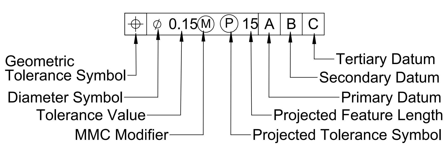
11. What is feature control frame in GD & T?

Feature control frame in gd&t is used to define gd&t tolerance conditions applied to a feature. Generally it includes gd&t tolerance control symbol, reference datum plane, tolerance value and gd&t modifiers.

This image shows feature control frame example in GD&T.
Feature Control Frame in GD&T
12. What is the tolerance zone for gd&t perpendicularity tolerance?

When gd&t perpendicularity tolerance is applied over the surface, the tolerance zone will be two parallel surfaces, planes, or lines perpendicular to the datum plane. All points on the controlled surfaces should lie within these limits.

Whereas when applied to an axis. The tolerance zone will be a cylinder boundary around a true axis. All points of the axis of the controlled feature must lie within this cylindrical boundary.

13. How to measure perpendicularity tolerance?

When applied to the surface, perpendicularity tolerance can be measured in the following ways:

  1. Square Ruler Block and Surface Gauge.
  2. Dial Gauge
  3. CMM or VMM machine.

Whereas when applied to an axis Go-No go gauges are the best and easiest way to measure the perpendicularity of a hole or Pin.

14. What are the applications of circularity tolerance in GD&T?

Circularity tolerance can be applied to cylindrical, conical, or spherical surfaces. Circularity tolerance in gd&t is used where a section of the part is critical only. For example, circularity is used to control bearing inner diameter and shaft outer diameter. It helps in providing more flexibility to the manufacturer while solving the purpose.

15. Why Runout tolerance is used?

Runout tolerance is used to control the total variation in a circular or cylindrical feature when the part is rotated about the true datum axis. Circular runout and total runout are applied to rotating shafts such as drill bits, shafts, vehicle axles, engine transmission parts, etc.

16. What GD&T tolerance require datum plane?

Following GD&T tolerance require datum plane:

  • Perpendicularity
  • Angularity
  • Parallelism
  • Position Control
  • Circular Runout
  • Total Runout
  • Concentricity
  • Symmetry
17. What are virtual conditions in GD&T?

Virtual conditions in GD&T are used to define the condition of a feature when MMC or LMC is applied.

Virtual Condition = MMC – Geometric Tolerance

18. What do you understand by MMC and LMC modifiers?

MMC stands for Maximum material condition whereas LMC stands for Least Material Condition. For a hole, Smaller size of the hole means hole is at MMC whereas larger size of hole means, hole is at LMC.

For a shaft, larger size of the shaft means the shaft is at MMC whereas smaller size of shaft means the shaft is at LMC. 

19. Why MMC is preferred while applying gd&t tolerance?

MMC is used in GD&T to provide additional tolerance.

20. What is a typical application of LMC?

LMC is used to control the size and position of a hole and the thickness of a material. For example, LMC is used to control part thickness to ensure a part is having sufficient strength in the least material conditions.

We will keep adding more questions to Top GD&T Interview questions and answers for mechanical engineers. Please add your comments or questions on GD&T interview questions.

11 Responses

Add a Comment

Your email address will not be published. Required fields are marked *